This thread has been locked.

If you have a related question, please click the "Ask a related question" button in the top right corner. The newly created question will be automatically linked to this question.

INA233: BIDIRECTIONAL CURRENT SENSING

Part Number: INA233

Dear Friends ,

   I want to know if it is possible to sense positive as well as negative current direction in the battery voltage and current sensing using INA 233.

I am working on an  application where I need to sense the current direction .i.e I need to know if the battery is in charging or discharging mode.

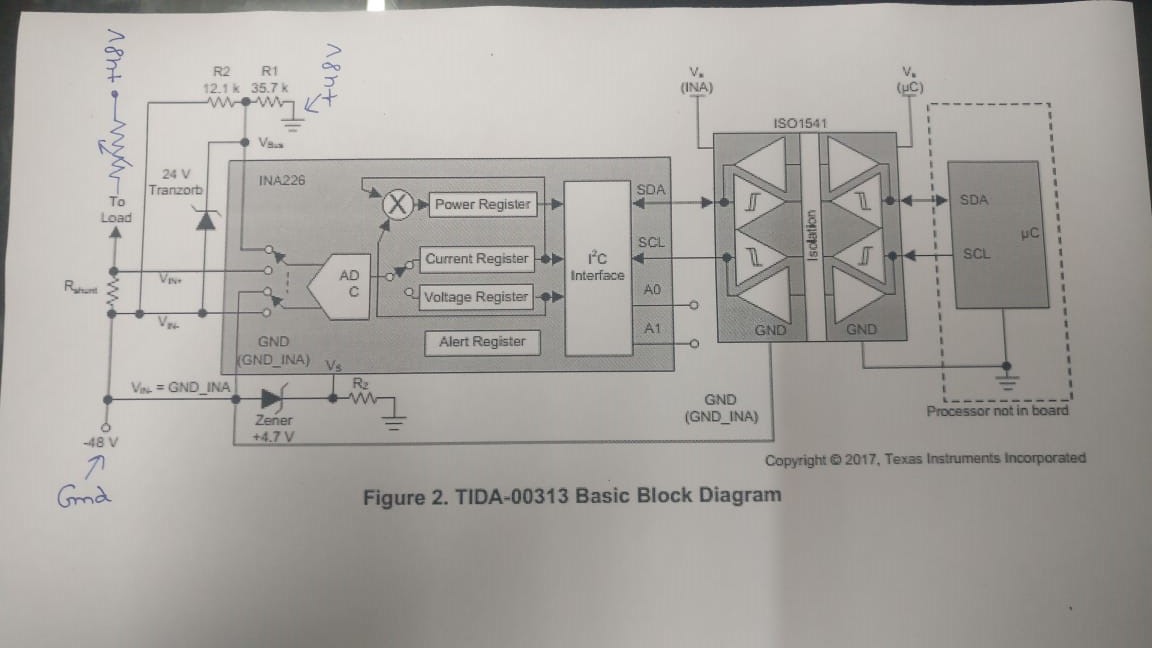
I am using the following hardware :

The only difference is that I am using INA233 instead of INA 226.

I want to know if i can use the above design to sense the bidirectional current flow .i.e if the current flows from battery charger to charge the battery or the current flows from battery to the circuit .

As read there is a register D1H(reg address) whose 15th bit indicates the direction .

How can i use above design to read battery charging as well as discharging current with polarity .

Do i need to make some changes with respect to the shunt positioning.Or will it work in the same way as depicted in the image.

  • Hi,

    INA233 is a bidirectional current and power monitor. So yes it can sense positive as well as negative current.

    The reference design can be used to make bidirectional measurement without modification. If the current reverses direction, the INA233 will report a shunt voltage of opposite polarity in register D1H. Polarity is indicated by the sign bit (MSB).

    In other words, functioning of the circuit is independent from the the current direction.

    Regards, Guang

  • HI Guang Zhou ,

         Thanks for the reply .That resolves my concern regarding the doubt .However I have another question related to the same .

    In my test set up I am supplying +48V of the smps supply to Gnd of circuit and Gnd of the smps supply to Vin-.

    I have connected a rheostat as load to vary current for testing. I want to know if i change the smps supply polarity will the IC INA233 work as there is a zener diode for Ic supply generation by dropping the voltage.

    What is the best way to test the both side current flow in same setup.Please check if the circuit attached is fine for testing or do i need to make some other change.

  • Hi Jitender ,

    Thank you for the confirmation.

    Regarding the second question, there are several possible ways I can think of to accomplish the test.

    The first is similar to what you drew, but place the -48V node at some negative potential, such as -10V so that the regulator still functions. A second source (+48V as you drew) can be placed with the rheostat. Adjust the second source so that it either sources or sinks current. The resistor values need to be reevaluated. This option is the most involved however, therefore I recommend either of below:

    The 2nd option - remove Rshunt, replace it with a floating voltage source whose amplitude and polarity can be adjusted. This voltage source simulates the shunt voltage.

    The 3rd option - leave the circuit as is and simply reverse the VIN+ and VIN- pins of the INA233. Doing so is equivalent to having current reverse its direction.

    Regards, Guang

  • Hi guang , 

      Thanks for the reply .

    I have connected another supply to the load .I have made both the supplies ground common.

    Now when i change the direction of the current of this new second power supply of 24 Volts(variable) I am able to see the +ve as well as -ve mv on the shunt as well as on the register data for following registers

    :

    1. REG ADDRESS : D1H (MFR_READ_VSHUNT): goes from some 1976 value to 64824 on changing the direction of current flow.

    2. Reg Address : 89H(READ_IIN) :goes from some 1844 value to 64952 on changing the direction of current flow.

    My concern is How to calculate current from the register values.

    The shunt used is 0.001 ohm , Max current to be read is 100A.

    Mfr calibration register value i m using as 1678(which comes out after calculating as per the formula 1 and 2 in section 7.5.2 in the datasheet)

    My dc ampere meter shows  1.768 A current.

    I am unable to relate the register read value from the (D1H or 89H) REGISTERS WITH the actual value of 1.768 A as shown on the dc ampere meter.


    Also as i read in datasheet :

    It says READ_IIN COMMAND is calculated by multiplying decimal value of READ_VHSHUNT_OUT and decimal value of MFR_CALIBRATION register.

    In my case if i try to compute using the same the value of the 

    theoretically READ_IIN should come out as  : 1976(shunt reg read) * 1678(Mfr_calibration reg) : 3315728

    whereas practically the register READ_IIN is giving me value 1844.

    Please help me correlate above reading and let me know where Am i wrong.

    To conclude : I have 2 queries :

    1.  I am unable to understand the READ_IIN reg value which is coming and which should come by multiplying READ_VHSHUNT_OUT and MFR CALIBRATION REGISTER.

    2. How to convert the READ_IIN value to real world DC ampere coming from the dc ampere meter.Does the register shows value in uA,mA or do i need to multiply it with a conversion factor which would work in the whole range of 0 - 100 A.

    3.Please help me with the values i am using in my setup to correlate the current measured.


  • Hi Jitender ,

    1 The description in the READ_IIN section is not entirely accurate. A few words are missing, it should have been something like “The value returned … is calculated by taking a portion after multiplying ….”.

    2 To convert READ_IIN register value to real current, simply multiply by the current LSB. With your register value, the current=1844*0.00305=5.63A.

    3 I think you got all the basics. The remaining task is to improve the accuracy of the setup. If you make the shunt resistor 10mOhm, you should already see improvement. But before you do, you should measure the input differential voltage closest to INA233 input pins to verify that you’re reading ~5mV, not 1.768mV as expected in theory. If true, it means the INA233 is working correctly, rather there are parasitic resistances in the setup that need to be eliminated. 

    Please let me know your findings. I’ll be more than happy to assist further.

    Regards, Guang