This thread has been locked.

If you have a related question, please click the "Ask a related question" button in the top right corner. The newly created question will be automatically linked to this question.

LM741: Looking for a Good Op-Amp Suggestion for a pulse detecting with 0.5ms pulse width

Part Number: LM741
Other Parts Discussed in Thread: TLV3401, TLV1701, LM311

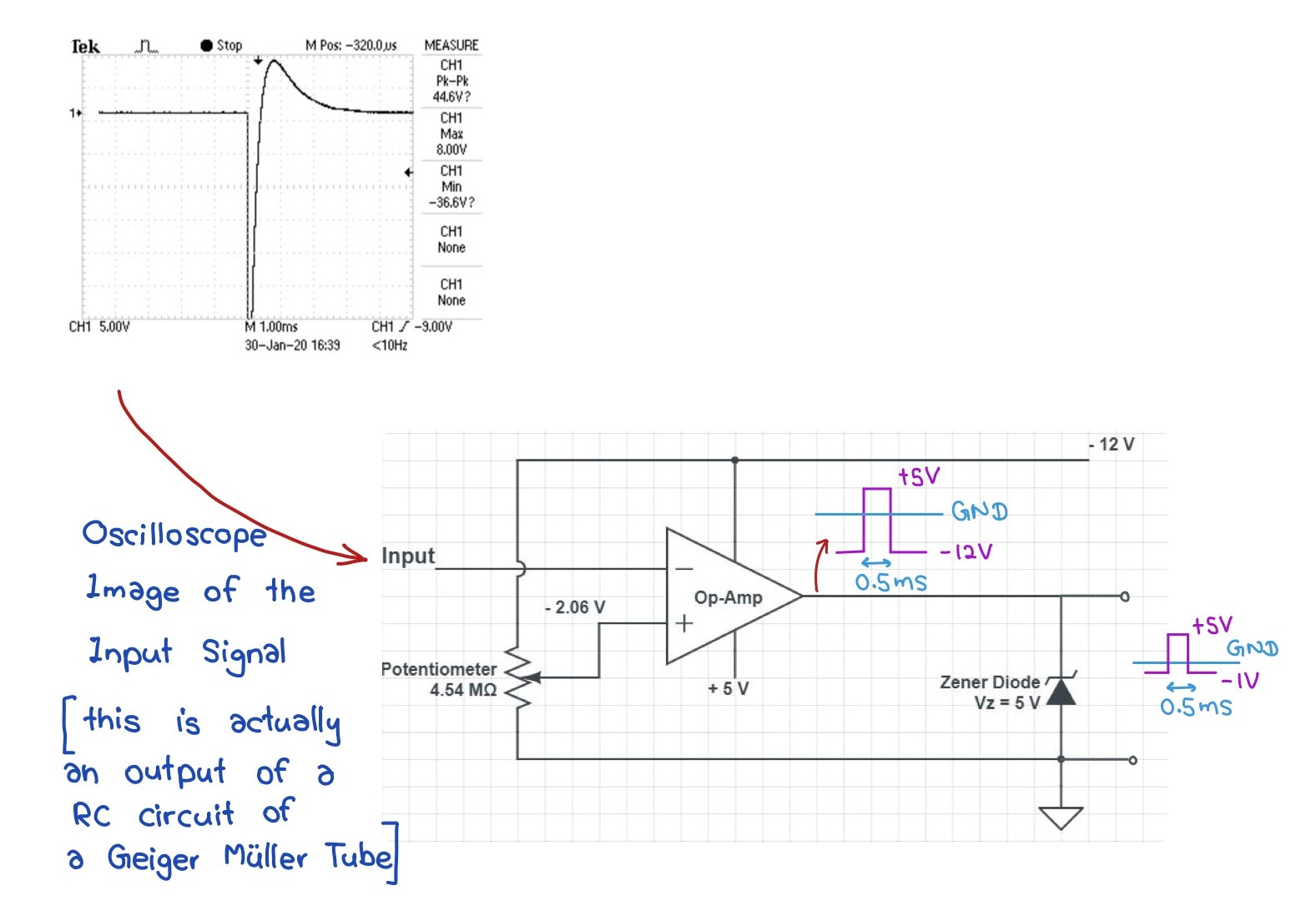
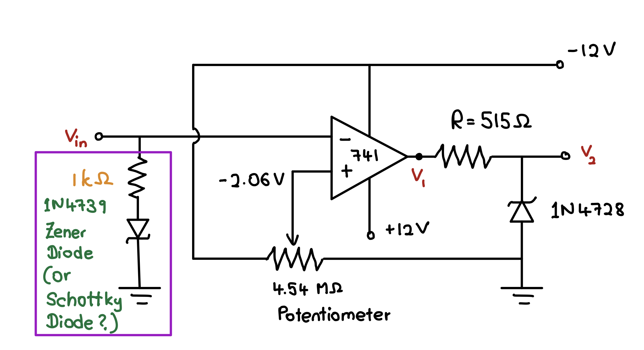
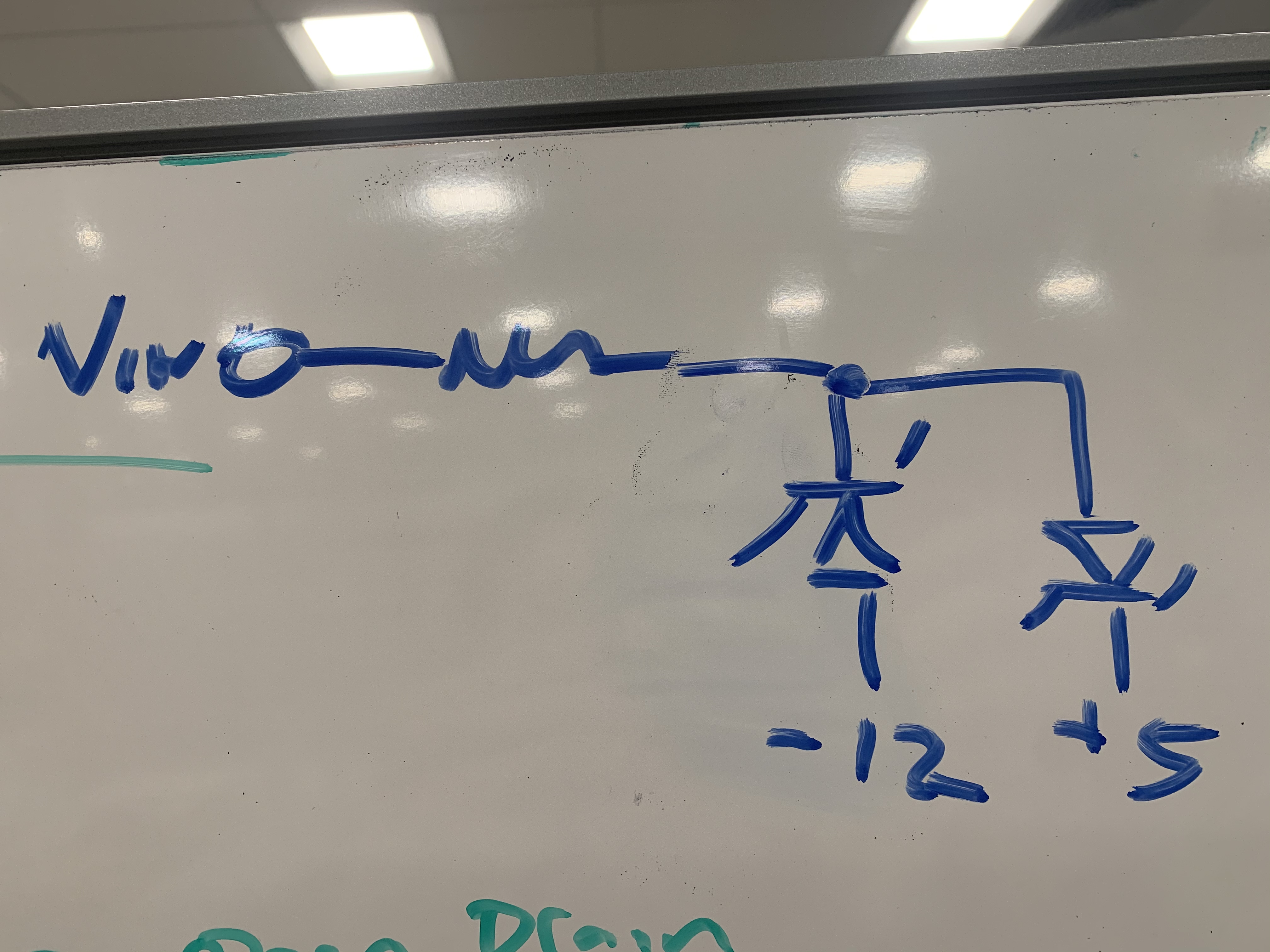
Hi! I am currently working on designing a Compactor Circuit for a pulse signal from GM Tube as shown in Oscilloscope! It would be grateful, if you could help me to figure out the best Part number for the Op-Amp IC and the Zener Diode for the circuit below. The specialties I am looking from the Op-Amp IC is it can detect 500 microseconds pulses and getting a TTL pulse for the computer with ultra low noise (Since TTL pulse output, I am wondering to supply +5V for +Vcc of the IC ).  The purpose of the Zener Diode for shapping the pulse for TTL output. I worked with 741 series ICs, But I was suspecting about the noise and setting +5V for +Vcc!

I would appreciate any advice. 

Thank you very much in advance for your help!


  • Hello Lakshitha Lathpandura,

    Welcome to the forums. Your circuit is stressful and harmful to the op amp.  I added some protection and changed to a comparator. 

    I'll let the comparator team refine this circuit.

    TLV3401.TSC

  • Hi Ronald!

    Thank you very much for your reply and I really appreciate your time! I examined the suggested circuit and I read the Datasheet of TLV3401IP.

    However, I need to detect the negative peak of the input pulse (between - 2.0V to -4.0V) (please see the Oscilloscope Image) for the comparator circuit! Because I am going to improve the input pulse by a RC Circuit and and after it the positive tale will be diminished. Since TLV3401 IC works in 0 to 16 V supply voltage, I am in a doubt of using the suggested IC for a comparator with negative reference voltage (Vref = -2V)!

    Further, this GM Tube is not for a portable device and it is for an IPE (Inverse Photo-Emission) spectrometer! Therefore, ultra low noise also I am expecting! The output of this Comparator circuit (TTL pulses) will be fetched to a NI USB-6009 DAQ device for LabVIEW software in the Computer!

    I look forward to hearing from you back!

    Thanking You!

    Best Regards;

    Lakshitha 

  • Hi Lakshitha,

    You could also configure a comparator in a split supply configuration so that your -2V signal will still be within the common mode range of the device. Something like the TLV1701 could work for your application. It is an open drain comparator with 300uV input offset.

    Looking at the datasheet of your DAQ, it seems that it can take +/-10V single ended measurements, so the output of the TLV1701 with a split supply configuration should be compatible with your DAQ.

    http://www.ti.com/lit/ds/symlink/tlv1702.pdf

    Regards,

    Jonny

  • Lakshitha

    Do you have the option to power the comparator from split supplies?  We have comparators such as LM311 that can be powered from split supplies for the input stage and still level shift the output with respect to ground.

    Chuck

  • There has not been any activity on this thread for a while, so I will be closing it.

    If you need further support, feel free to reply or open a new thread.

    Thanks

    Chuck

  • Hi Lakshita,

    are you sure that only -2V...-4V are coming from the Geiger Müller Tube? Your scope plot shows a much larger pulse.

    Can you post a schematic of your Geiger Müller tube showing the HV supply voltage, "sense" resistor, "load" resistor, caps for decoupling and AC coupling, etc.?

    Kai

  • Hi Chuck!,

    I am sorry that I could not reply until now! Wednesday and Thursday our detector had a leak and then we had to get it back working!

    I really appreciated your reply by suggesting LM311 and I read the datasheet too. I think it's Fast Response time is important for us. We have a "Canberra 1400 NIM Bin" which provides +24, +12,-12,-24 Voltage supplies! 

    Here I have attached a circuit diagram that I suppose to build using LM311. Since I do not have +5V supply, I can use +24V (or +12V which I already plan to use for powering up the IC) to make a voltage divider with the ground using 2 resistor network. i hope it is not make problem due to the current drop! If you think I did not understand the point you mentioned in the first message, please kindly refine the circuit diagram! 

    Meanwhile, I built a circuit using 741 IC which gives a basic idea (attached below.) The purpose of the Zener Diode is for limiting the hight of the square pulses for TTL output! 

    So my plan to replace the 741 IC and the Zener Diode using a LM311 by expecting fast response and low noice interference for TTL pulses! Thank you very much for your time and kind attention!

    I look forward to hearing from you back!

    Thanking You!

    Best Regards;

    Lakshitha 

  • Hi Kai!

    Thank you very much about your reply! I am sorry about the confusion. I meant that I want to detect negative peak by using a comparator with reference voltage around -2V for the 3rd pin of the Op-Amp IC. We are developing electronic read-outs for a GM Tube to get counts for NI USB-6009 DAQ device which is linked to LabVIEW software in the Computer!

    Here is the full circuit, I have developed so far! I have attached Oscilloscope Images of some connection points to make it sense! This GM Tube is consisted with a gas mixture of He and Iodine Vapor (Total ~20 torr) with 43pF inherent Capacitance. This detector is capable of detecting VUV photons (10eV) with the help of SrF2 window and gas mixture cut off! So my intend is to reduce noise and other interferences to read real counts. Therefore my 1st question was which IC (Op-Amp, Comparator) is suitable for this purpose instead of general 741 IC. My 2nd question (If you can help me) is what are the good values I should use for Cc and Cs Capacitors! Sometimes I feel Cs Capacitor is not required too! It seems it keeps low count rate!

    I feel Rb is around the right value! Because when it lowered to 2MOhms, I noticed multiple peaks in a count (see the last separate Oscilloscope Image). It may result of multiple Geiger Discharging in a count since it does not quenching well externally. Higher Rb values reduce the count rate!

    Thank you very much for your time and kind attention! I look forward to hearing from you back!

    Thanking You!

    Best Regards;

    Lakshitha 


  • Hi Lakshitha,

    have you thought about inserting a 100k resistor, or similar, between cathode of Geiger Müller tube and signal ground? This would give you a positive pulse and eventually simplify the circuit.

    Kai

  • Hi Kai!

    Thank you very much for the reply! Actually, I could not mention you that our Cathode is always grounded with the Ultra High Vacuum (UHV) Chamber! Therefore we can not introduce any other circuit for it! Onetime I tried by setting negative Bias Voltage to the center wire (converting into a cathode instead of Anode). Then I got a pulse. But it is not good for center wire, because corrosive Iodine (Quenching Agent) will be deposited on it and it will reduce the count rate with long period of time! Do you have any suggestion for Cs and Cc Capacitor Values? 

    Thank you very much for your kind attention! I look forward to hearing from you back!

    Thanking You!

    Best Regards;

    Lakshitha 

  • Hi Lakshitha,

    usually, the manufacturer of Geiger Müller tube is recommending the values for the resistors and caps. Do you have a datasheet of your Geiger Müller tube? Or is it self-fabricated?

    Kai

  • Lakshitha

    Kai is giving you some excellent support.  I just wan to make sure that you do not violate the input range of the comparator with the input signal.  Your oscilloscope screenshot is showing a signal going beyond -25V.  Just make sure you limit any large negative transients with a schottky diode and a series resistor.  Same goes for the output if you are using a zener to limit the output to +5V, that will need a series resistor as well.  I think you knew that and your drawing was meant to be simplified but I wanted to make sure just in case anyone else is following the thread.

    Chuck

  • Hi Kai!

    Thanks for the reply! No . It is a home-made one! So I developed the circuit to this level after reading about Text books and Research Papers! But any literature does not provide details about the relationship between Capacitor Values (Cc and Cs) and the pulse height or shape!

    Thank You very much for the support Kai!

    Best Regards;

    Lakshitha

  • Hi Chuck!

    Oh, I completely unaware of it! the comparator receives the pulse (Vmin = -35V) that violates the input range! I posted the complete circuit I have so far and Oscilloscope Images are based on it! Only change I will add to this circuit is 2 bypass capacitors (0.1uF) to the supply pins of Comparator IC to reject any violation of the supply voltage. So, is that my circuit should be like this? (Please see the attached circuit below!)

    I put a Zener Diode which has Vz ~ 9V for it. But if you say to put Schottky Diode, can you suggest me a part number? (I assume the purpose of Schottky Diode for this application is that considering heat generates through the diode). I can put another resistor in between Vout and the last Zener Diode in series!

    I was about to place the order for LM311P today, but I postponed it until this gets clear! 

    Thank You very much for the support Chuck!

    Best Regards;

    Lakshitha

  • Hi Lakshitha,

    The BAT54 is a good part to use.

    I would change your input protection scheme to something like this: 

    Regards,

    Jonny

  • Hi Jonny!

    Thank you very much for the explanation and the suggestion. Really appreciated!

    Thanking You!

    Best Regards;

    Lakshitha


  • Hi Lakshitha,

    Cgm and Cs are rather big capacitances. When the Geiger Müller tube is triggered Cgm discharges partially through Cs. As this current isn't limited at all, a huge current pulse can flow which can damage the tube or cause secondary triggerings. Have you thought about inserting a current limting resistor?

    Here are some very interesting links:

    Kai

  • Kai,

    Thanks for your recommendation as always, a current limiting resistor in series with the input will be more safe in order to prevent large discharge from your caps.

    Regards,

    Jonny

  • Hi Jonny!

    I was going through the data-sheet of BAT54 as you suggested! But it is available in Surface-Mounted Technology. Therefore I found SD103A Schottky Diode which has Hole-Through Technology and Vf=0.6V (If=200mA) is useful! If you think I missed something by choosing this part, please kindly let me know!

    SD103A Datasheet.pdf

    Thank You very much for the support!

    Best Regards;

    Lakshitha

  • Hi Kai!

    I do not know how to express "Thank You" for this big support! I went through all 4 links you gave me and I found the first link is more useful and I am decided to build that circuit as an initial step! I measured the inherent Capacitance of the GM Tube using Capacitance Meter which is 43.2pF. I noticed that when I increased Cs from 300pF to 1000pF, the Vpk-pk of the output dropped from 12.2V to 7.2V (Cc=18.2pF)! I think I will use I suitable higher capacitance for the keep signal in between input range of the comparator! Further I will add 2 Schottky Diodes for more protection for the Comparator IC! 

    I did not think about a current limiting resistor! Should I place something around 1MOhms or 470 KOhms?

    Thank you very much for the explanation and the suggestion. Really appreciated!

    Thanking You!

    Best Regards;

    Lakshitha

  • Hi Lakshitha,

    yes, I would try to insert a current limiting resistor between the Geiger Müller tube and Cs. I think something between 1k and 100k should be appropriate. Maybe a bit more.

    Kai

  • Using a current limiting resistor in the 100's of kohms is appropriate.  Depending on what comparator you are selecting, be aware of the input bias current and make sure the resistor does not create too much of a voltage drop at the worst case input bias current level.

    Chuck