This thread has been locked.

If you have a related question, please click the "Ask a related question" button in the top right corner. The newly created question will be automatically linked to this question.

More on buffer to drive 50 ohm line and load

Other Parts Discussed in Thread: OPA810, THS3491, OPA140, TINA-TI

Dear Support,

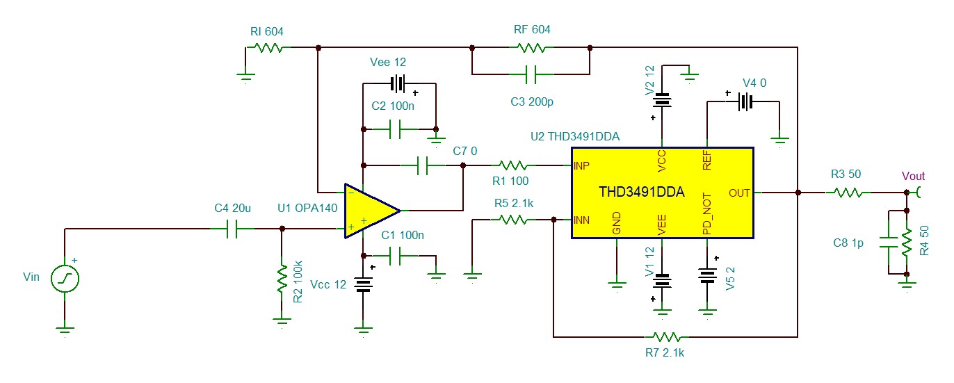
I have to design a unity-gain buffer to allow a low-noise lab-grade voltage amplifier to drive a 50 ohm load via  50 ohm coax cable.

The voltage amplifier driving the buffer needs to see a load impedance of 10k or higher. The amplifier output is in the range -4V, 4V.

The buffer specs are the following:

- voltage supply: not higher than +/- 12V

- power consumption: no limit

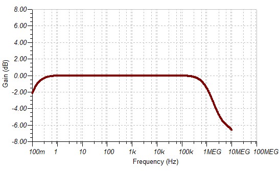
- gain: 1V/V across a 120-150 Khz

- voltage swing in output (50 ohm load): -4V, 4V

- output driving: 50 ohm coax line terminated on its impedance

( the buffer should then have a G of 2V/V to compensate for the 50ohm/50ohm partition)

- input coupling: DC, AC (BW: 0,1 Hz to 120-150 Khz)

- THD: -80dbc for the second harmonic

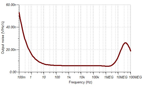
- noise: frequency corner of the flicker noise lower than 10Hz, low noise current to allow having an input high-pass filter

Could you please help me in selecting the best op amp (or more than one amp) to do the job.

Thank you for your help.

Best Regards,

Alberto

  • Hello Alberto,

    I thank you for giving a lot of details upfront. 

    I will look into this on Monday.

  • Yes Alberto, great detail in your requirements. 

    1. That -80dBc into 100ohm load +/-4V output (+/-40mA) through 150kHz is the tough one. Need to start out with quite a bit of loop gain at that frequency to have any hope, which means a lot of GBP. 

    you might look at the OPA810 at gain of 2 on +/-5V supplies. Being RRout +/-4V output should be ok. Plenty of output current and slew rate margin. (you said amplifier output of +/-4V is that at the output pin assuming the backmatch loss. If you actually need +/-4V at the matched load, then the +/-8V output will need maybe +/-10V supplies and might push the output current available too hard). 

    2. Being JFET input, very low input noise current and bias curent. AC coupling will be fine. 

    There does not appear to be a 100ohm HD plot, but the 500ohm curve here says you have 40dB degradation range to still hit -80dBc decreasing the load to 100ohm and increase the swing from 2Vpp. MIght make it at 150kHz, Actually the curve does not quote a Vpp swing (that is a mistake, but often it is 2Vpp for this kind of curve). 

  • Dear Ron,

    thank you for your prompt feedback.

    I have just seen the OPA633, which seems quite interesting. In particular, fig.3 and 4 in the data sheet show 'composite' not-inverting/inverting amplifier with the 633 'in-the-loop'.

    In my case, I need a G=2V/V in order to have G=1 right on the 50ohm load (taking into account the 50ohm output resistor).

     I also need an input resistance not lower than 10K (50k to 100k is even better). Bandwdith should be DC->120Khz (150kHz max).

    I have to consider a high-pass RC filter right at the input of the buffer (fc= 0.1 Hz), so R would be quite large to keep the C value reasonable.

    I guess, a FET-input op-amp would be a must as front-end.

    Thank you for your help.

    Kind Regards,

    Alberto

  • Dear Michael,

    thank you for your reply.

    Unfortunately I need a voltage swing of +/-4V right on the 50ohm load. As you pointed out, I would need a dual supply in the

    range +/-10 to +/-12V. I have just seen the OPA633: this op amp could open to a 'composite amp' solution.

    What is your opinion ? If it could do the job, I would need some help to fulfill all the specs, also in terms of bandwidth

    and input impedance. Mine is a 'low-noise' application, so I 'do not want' bandwidth in excess of 120-150 Khz.

    Thank you again for your help

    Kind Regards,

    Alberto

  • those are conflicting goals, you cannot deliver -80dBc at 150kHz with a 150kHz BW. You can bandlimited the overall response for lower integrated noise, but not in a brickwall sense. 

    Composite amps come with a lot of other issues (stability and motorboating are typical). I usually use the fastest highest slew rate part the project can afford for the imbedded power stage - start with the THS3491 and work down from there in choices.

  • Dear Michael,

    I have just simulated the reference design of the THS3491 available on the TI web site .

    I have changed the Gain to 2V/V and set the Rf and Rg to 25k, so to reduce the bandwidth to about 1MHz.

    The noise is VERY high, 10 uV/sqrt(Hz) at 1 Hz. This is 10 times higher of the output noise of my lab-grade voltage

    amplifier. To this purpose, this current feedback does not fit my requirements.

    I have also simulated a composite OPA140+OPA633 buffer and the noise a low freq (<10Hz) is less than 20nV/sqrt(Hz).

    What is your opinion ?

    thanks a lot for your time

    Alberto

  • yes that looks right 

    1. The THS3491 was only suggested as the imbedded power stage not a standalone stage - in the composite, the noise of the imbedded amplifier is reduced by the Aol of the input stage so will not matter, 

    2. The THS3491 is a current feedback, raising the R's to 25kohm has killed the BW and noise

    3. I have not specifically looked at the OPA633 composite you reference, but again the problem will be that -80dBc target at +/-8V swing into 100ohm load at 150kHz - that never simulates so hard to predict what it would be unless there is some lab data on that composite. 

  • Dear Michael,

    please find a tentative schematic of an embedded amplifier with OPA140 and THS9134:

    the current feedback has been set to a G=2 with the suggested Rf and Rg.

    This is the AC transfer function:

    here is the noise and transient:

    Could you please suggest any modification/improvement to the circuit ?

    Thank you so much for your time.

    Regards,

    Alberto

  • Hey Alberto,

    Looks pretty good to me, what would you like to improve? 

    To avoid motorboating, bring the supplies into the THS3491 1st then RC filter back to input stage supplies- also, to make sure there is DC bias point on power up, put a 10kohm resistor to ground on the THS3491 V+ input. 

  • Dear Michael,

    thank you for your advices.

    Please, have a look at the noise simulation. You can spot a peak at high freq, similar to the one shown by a TIA with a capacitive load.

    I do not understand the reason and the source. The circuit has a low pass filter 'built-in' thanks to the capacitor across the feedback resistor.

    However, the gain noise increases at high frequency.

    Last issue: TINA-TI gives a THD of 65% ! Not 0.065%... not even 0.65%... I am doing something VERY wrong ?

    Thank you for your time.

    Best,

    Alberto

  • Just for reference, this is the TINA-TI project:AC_OPA140_THS3491.TSC

  • Morning Alberto, 

    Well whenever you do this kind of composite you are injecting a prop delay inside the loop - the next step would be to set up for a LG phase margin sim. But that noise peaking does not look too bad actually. 

    As for distortion, let me assure you the requisite terms to accurately produce that data are not in the simulation macromodels - HD2 is not well simulated even in the full cadence design models. 

    Your problem now is more simulation approach oriented - one trick is to make sure the time record starts as cosine at time zero not a sine - that gives an initial dv/dt of zero which improves the initial transient response that eventually gives you the HD terms. But that will still not give you a reliable answer - only the bench will in this case. 

    Again, while these composites are kind of fun and interesting, if you can find a single op amp stage that will do what you want, the path to success is less fraught with hazard. I still think something like the OPA810 should merit some attention.