This thread has been locked.

If you have a related question, please click the "Ask a related question" button in the top right corner. The newly created question will be automatically linked to this question.

Stability of OP297 circuit

Other Parts Discussed in Thread: OPA277

We are using the following circuit to generate a -10.00 volt DC reference:
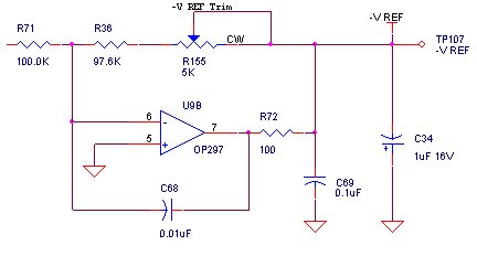
The input to this circuit at R71 is 10.00 volts DC.  We adjust R155 so that the voltage at -VREF is -10.00 volts DC.  At about 20F, the output takes a sudden shift of about 8 to 10 millivolts.  The 10.00 volt input stays constant at this time.  The output will remain shifted for several minutes and then shift back.  This occurs during a temperature test cycle where we change the ambient temperature from room temperature to 0F at a rate of about 2.5 degrees Farenheit per minute.  This shift causes a major upset in our circuit operation.  We suspected that the problem had something to do with the potentiometer, so we replaced it with a fixed resistor.  The problem remains even with the potentiometer out of the circuit.  Can you give us some ideas as to what might be wrong?

  • I just realized that this circuit is not using a TI part (the OP297 is an Analog Devices part).  With prefixes for TI parts that are "OPA" and prefixes for Analog Devices parts that are "OP"; I mistakenly thought that the OP297 was a TI part.  My apologies to the community.  Can you suggest a TI drop-in replacement that might work in this circuit?

  • Hi John,

    What are the power supply voltages on the unmentionable op amp? I think we can come up with a recommendation for an alternative.

    Regards, Bruce.

  • Hello Bruce,

    The part is being powered by +/-15 Vdc.

    John Homa

  • John,

    I don't see an obvious problem with the circuit other than the inferior op amp from a problematic supplier.

    I recommend the OPA277, which will surely solve all problems. You could build a separate test circuit so that if any other circuit components are defective, blame would be assigned to the errant op amp used in the first circuit.

    You may want to consider the alternative trimming arrangement I have shown. The 5k pot is used in a true ratiometric mode of operation, not as a variable resistor. This makes the trimmed voltage insensitive to wiper contact resistance. I realize that you eliminated the pot as the source of your issue, but I think this is good practice. Also, I admit it, I have this thing about getting the voltage on pots down near ground, when possible.

    The node VF1 is just a probe point as I checked the circuit for stability in Tina spice.

    Regards, Bruce.