This thread has been locked.

If you have a related question, please click the "Ask a related question" button in the top right corner. The newly created question will be automatically linked to this question.

OPA2388: peak-hold detector circuit affected by opamp input leakage current

Part Number: OPA2388
Other Parts Discussed in Thread: OPA2192, OPA388

Hello,

I am struggling with a peak detector circuit based on the OPA2388, and it just does not want to work!

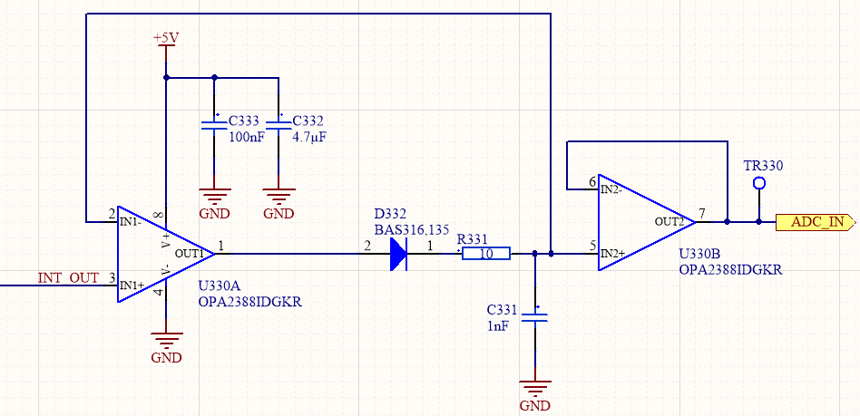
I have eventually reduced it to this:

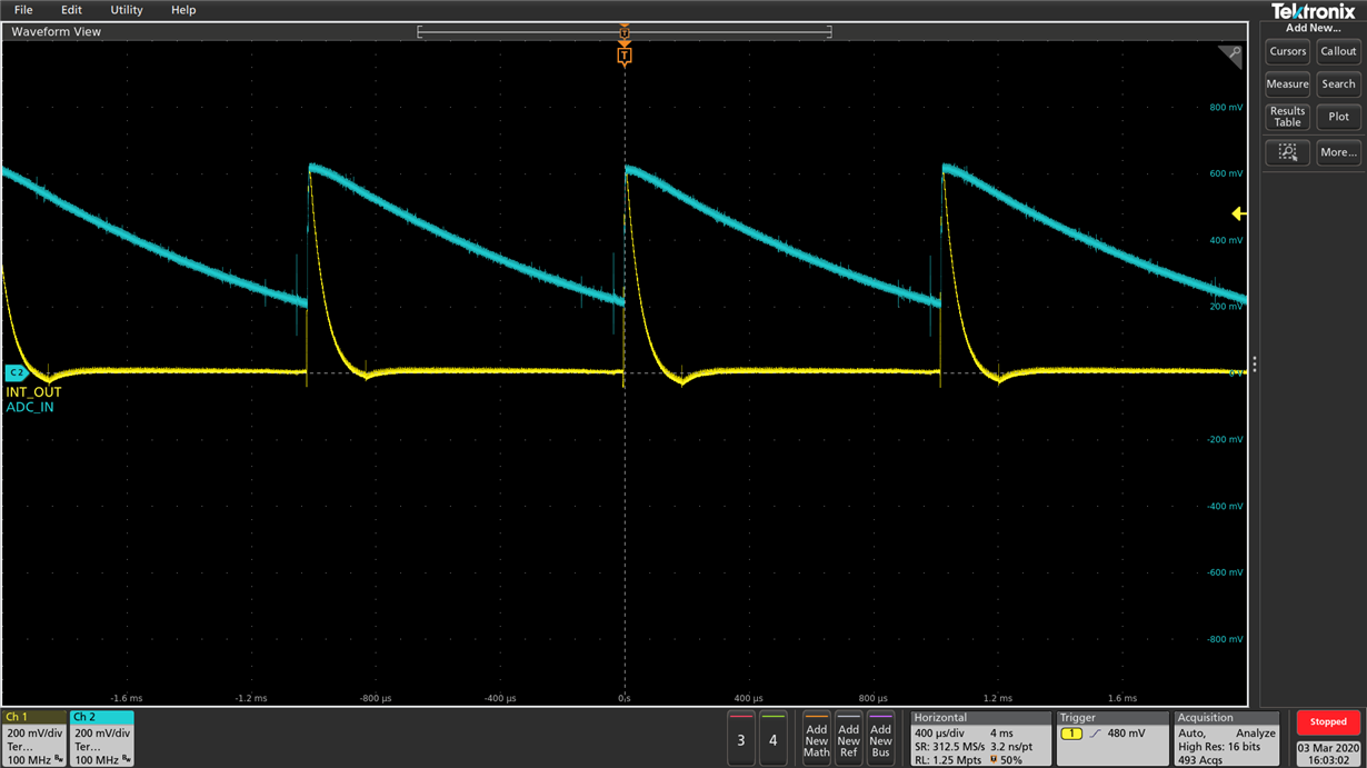
What I get from it, when appropriately stimulated with a repeatable input signal is this:

I do not understand why the C331 capacitor is not holding the charge, and the only thing I can blame it on is on the input leakage current of the opamp input. The datasheet indicates am input bias current of less than 1nA, but it indicates this is with an Ri=100kOhm. I am not sure what this Ri is referring to, is it an additional series resistance that needs to be added to the input of the opapm? If I consider the leakage of both opamp inputs connected to the C331 (about 1nA each) and the maximum reverse current of the diode (30nA) I estimate the decay on the capacitor must not be greater than 35mV during the 1ms period (which is the repetition rate of the input signal).

I must mention that I am explicitly not probing the capacitor voltage directly with the oscilloscope, to prevent the probe impedance from discharging the cap. I am only able to look at the output of the second opamp (which is in buffer configuration.

So any ideas? Is it not the OPA2388 the right one for the job? I have replaced both the opamp IC and the diode, just in case I was dealing with a faulty one, but that was not it.

Best regads,

Cristian

  • Hello Liviu Christian,

    First, do make sure that you are using a high quality dielectric, low leakage capacitor for the hold capacitor. Some of the better capacitor dielectrics are polystyrene, Mylar, PTFE, mica and C0G ceramic.

    Second, do make sure that the OPA2388 PC board has been thoroughly cleaned and all solder flux has been removed. If the solder has water soluble flux, then we recommend cleaning the board in an ultrasonic cleaner using DI water. The board should then be thoroughly dried in an oven or with a blow dryer.

    If you find the OPA2388 behavior is unchanged, then indeed it may be the OPA2388 that is loading the hold capacitor. The OPA2388 is a chopper input op amp, and even though the average input current may be much less than 1 nA, the peak input current can be considerably higher when the input switching is occurring and charge transfer takes place in the switching circuit. 

    One way to test this idea is to replace the OPA2388 with a non-chopper op amp. I suggest replacing the OPA2388 with an OPA2192 precision RIRO op amp that has a more conventional, non-chopper input. Its input bias current is rated at 20 pA maximum at room temperature. It is a higher voltage op amp, but operates just fine with a supply down to +4.5 V. Your +5 V supply should be good. Do make sure that the PC board is cleaned well after the op amp replacement.

    Let me know if that solves the problem.

    Regards, Thomas

    Precision Amplifiers Applications Engineering

  • Hello,

    Thank you for your prompt reply.  The capacitor is C0G dielectric. I do not have access to an ultrasonic cleaner, but I will put together tomorrow a separate new "clean" board with no flux residues to begin with.

    However, a fellow electronic engineer pointed out two things that could affect the capacitor charge:

    1. The back-to-back protection diodes described in Figure 42 on the datasheet definitely affect the output, should the difference in voltage between the two inputs of the 1st opamp exceed these diodes voltage drop

    2. The input current ratings indicated in the datasheet of the opamp are only valid if the opamp is operating in its linear region, otherwise they can be much greater. Is this true? In principle, the 1st opamp in my circuit is almost always operating in saturation, because as soon as the input signal drops below the voltage stored in the capacitor (which is at the level of the previous peak) which is also present at the inverting input of the opamp,  its output will swing all the way to GND trying to compensate (the feedback loop is essentially interrupted by the reversed biased diode in my circuit).

    Any thoughts on that?

    Thanks!

    Regards,

    Cristian

  • Hi Christian,

    Regarding your comments/questions:

    1. The back-to-back protection diodes described in Figure 42 on the datasheet definitely affect the output, should the difference in voltage between the two inputs of the 1st opamp exceed these diodes voltage drop.

    Yes, if the back-to-back input protection diodes were to become forward biased the input current would increase well beyond the normal levels. However, the input voltage would have to taken beyond the supply rails for that to occur.

    2. The input current ratings indicated in the datasheet of the opamp are only valid if the opamp is operating in its linear region, otherwise they can be much greater. Is this true?

    Yes. The OPA388 specifications listed in the Electrical Characteristics tables are for linear operation, with the exception of the Voltage output swing from rail (Vo) specification. That is an output slam test where the output is no longer operating within its linear operating range.

    In principle, the 1st opamp in my circuit is almost always operating in saturation, because as soon as the input signal drops below the voltage stored in the capacitor (which is at the level of the previous peak) which is also present at the inverting input of the opamp,  its output will swing all the way to GND trying to compensate (the feedback loop is essentially interrupted by the reversed biased diode in my circuit).

    In which case if the output is saturated then the output is no longer operating in the linear operating region. When that happens the op amp falls out of linear "op amp" operating mode and its electrical characteristics become severely degraded. You can expect the open-loop gain, voltage offset, input bias current, bandwidth, etc. to be degraded and unspecified. That may be the issue.

    Regards, Thomas

    Precision Amplifiers Applications Engineering