This thread has been locked.

If you have a related question, please click the "Ask a related question" button in the top right corner. The newly created question will be automatically linked to this question.

TLE2022M: Determine input impedance for this op-amp

Part Number: TLE2022M
Other Parts Discussed in Thread: TLE2022, TLE2021

Hello, 

I have a test circuit in which a sinusoidal signal of frequency 2MHz is applied to TLE2022 IN+ via SPDT switch. The switch is used to select amplitude of the 2MHz sine signal applied to TLE2022 IN+. I need help determining the input impedance (resistance, shunt capacitance) of TLE2022, I did not find a direct spec in the datasheet. I know ideally, the input impedance will be infinite but I am worried this impedance can go down for 2MHz input signal if there is significant shunt capacitance. 

I tried to get SPICE model for TLE2022 from TI's website but could not open the files in LTSpice. I do not have access to PSpice or TINA. Is there anyway I can open the part model in LTSpice?

Thanks!

 - Swantika

  • Swantika,

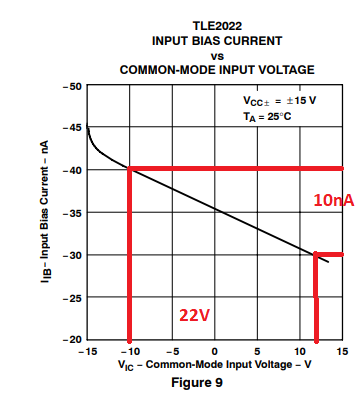
    The input common-mode resistance of TLE2022 may be calculated from the graph of IB vs Vic - see below.

    Rin_cm = ΔVic/ΔIB = 22V/10nA = 2.2Gohm

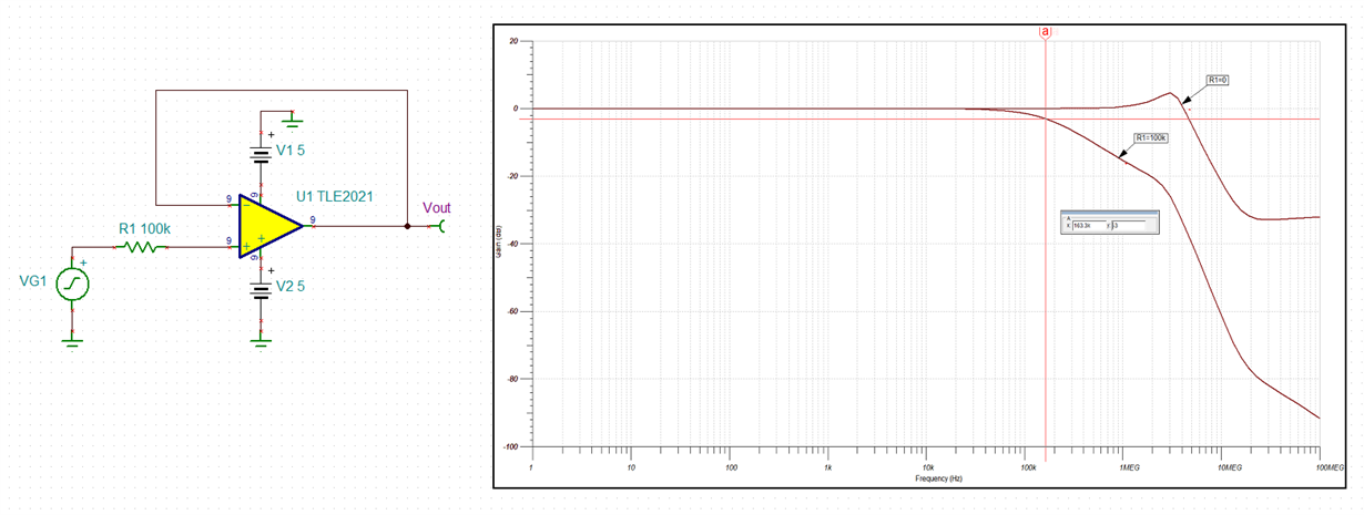
    The common-mode input capacitance may be simulated using circuit below.  

    Once you determine -3dB frequency, you may use it to back calculate the Ccm.

    Zc=1/(2*Pi*f*C), therefore, Ccm=1/(2*Pi*f*R) = 1/(6.28*163.3kHz*100kohm) = ~10pF 

  • Hi Swantika,

    I am able to import the TLE2021.lib into LTSpice, and able to run the simulation without issues. 

    Please download the PSpice model (in Zip format) from the TI's website, see the link below. Open the Zip file, and copy TLE2021.lib into LTSpice's LTspiceXVII\lib\sub directory. 

    You have to use .lib or .include command under .op SPICE directive to link the library file, TLE2021.lib. 

    If you are unable to get it working, please send me a private email via E2E. I am unable to support LTSpice directly due to license agreement. 

    Best,

    Raymond

  • Hello Raymond, 

    Thank you so much for your help. I am able to run the model in LTSpice now. I put the incorrect file in LTSpice sub directory earlier.

    Regards, 

    Swantika

  • Marek Lis, 

    Thank you for the excellent explanation. Exactly what I was looking for. 

    Regards,

    Swantika

  • Hi Swantika,

    keep in mind that the SPDT switch can also show considerable stray capacitance.

    Can you post a schematic which also shows the SPDT switch circuitry?

    Kai

  • Hello Kai, 

    Thanks for pointing out. SPDT switch schematic is shown below. We are using this switch for two different applications: 1) To turn on off p-channel JFET and 2) To select gain of receiver signal. 

    Let me know if there any inputs w.r.t. stray capacitance. 

    -Swantika

  • Hi Swantika,

    in the meantime I have had a look at your schematic. The parasitic capacitances within the ADG419 are no issue because 1n caps are sitting at the S1 and S2 pins which are much bigger than the parasitic capacitances of analog switch and OPAmp input.

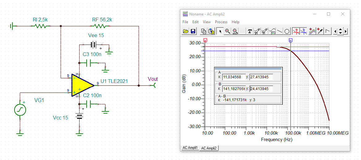
    But there's another issue. The TLE2022 is way too slow for your application. The TLE2022 is not capable to provide the desired gain at 2MHz as the simulation shows:

    swantika_tle2022.TSC

    You get a corner frequency of only 141kHz. You should choose a much faster OPAmp and/or split the total gain on two OPAmp stages.

    Kai