This thread has been locked.

If you have a related question, please click the "Ask a related question" button in the top right corner. The newly created question will be automatically linked to this question.

Query - OPAMP selection for NIC

Other Parts Discussed in Thread: TLV9062, TINA-TI

Hi,

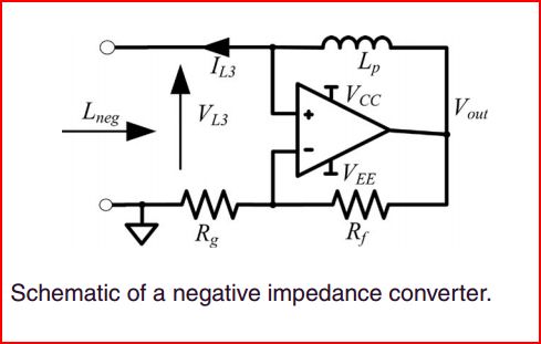
Kindly support us in selection of an OPAMP to design a 'Negative Impedance Converter (NIC)' for one of our EMI Filter applications.

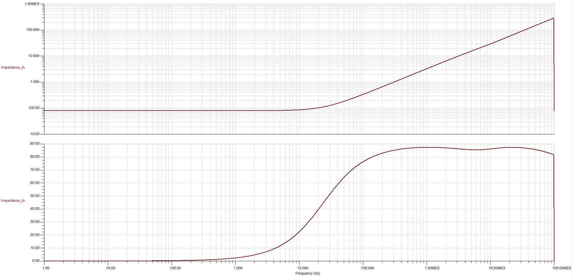
I watched your series of videos on stability of an OPAMP. Based on which, I worked on the simulation of negative Impedance circuit, but inductor on the positive feedback path affect's the stability.

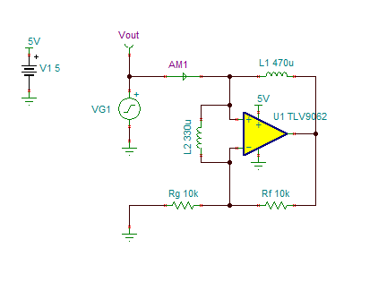
Please refer the below image for circuit diagram. (Values : Rf & Rg - 10K & LP - 470uH).

Note : One more inductor will be connected between Inverting and Non-inverting Terminal (330uH).

Kindly suggest how to improve the stability. Any external compensation is required. Desired closed loop bandwidth is Minimum 10MHz and above.

Regards,

Sadham Husen S.

  • Former Member
    0 Former Member

    Hello Sadham,

    Thanks for your question and welcome back to the forum!

    Other than a closed-loop bandwidth of 10MHz or above, do you have any further specification needs?  Perhaps this will help us to make a better part suggestion.  If you do not have any other needs, then the TLV9062 might be a good place to start.

    Though I've come across them before, I'm not terribly familiar with negative impedance converters.  Please allow me to dig into this some more and I will have an update for you tomorrow with my comments and/or suggestions for your application.

    Regards,

    Daniel Miller

  • Former Member
    0 Former Member in reply to Former Member

    Hi Sadham,

    I've got a few follow-up thoughts for you:

    1.  The typical feedback stability analysis will not work for this circuit because the usual stability analysis assumes you only have negative feedback.  With the addition of positive feedback, a different technique should be used.  The technique used for this type of circuit was developed by Tim Green and was referred to by him as the "Double 'L' Break."  See this presentation for some more details:  Dual FB Beta_plus and Beta_minus RevD.pptx

    2.  It looks like you want a negative inductor.  Have you tried achieving the same goal with capacitors instead?  From a quick online search, it looks like the same negative inductor effect can be done with a slightly different configuration that makes use of capacitors instead.  I bring this up because it looks like the current design you have requires some relatively large inductors.

    3.  Have you been able to simulate your design yet?  If not, I recommend you try our TINA-TI tool.  If you do use this free tool, you can save yourself some time by using the model I've built.  See the bottom of this message for the TINA file.

    4.  I went ahead an ran some simulations with a generic op amp in TINA-TI and got the following result.  It's better without the 330uH inductor than with it.  I would appreciate if you could explain the intended effect of this component.

    Regards,

    Daniel

    3487.NIC.TSC

  • Dear Daniel,

    Thanks for your suggestion.

    Please give me some time i will check on this.

    Regards,

    Sadham Husen S.

  • Former Member
    0 Former Member in reply to SADHAM HUSEN S

    Hello Sadham,

    Not a problem.  Feel free to post here again when you are ready.

    Regards,

    Daniel Miller