This thread has been locked.

If you have a related question, please click the "Ask a related question" button in the top right corner. The newly created question will be automatically linked to this question.

XTR111: Regulated current changes in different environments despite XTR111 state unchanged

Part Number: XTR111

We are developing a product that uses the XTR111 to regulate the current for a 4-20mA circuit.
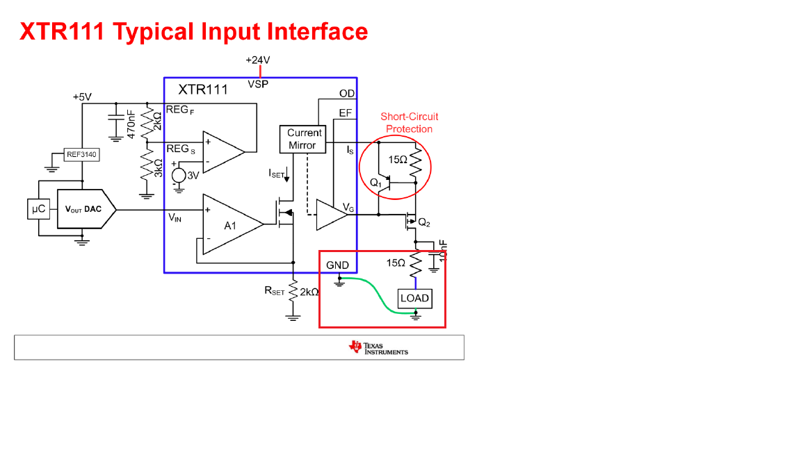
We have implemented the design as shown in the XTR111 documentation.

During testing, we found that the regulated current varies from one environment to another.
We could really use some help figuring out what to look at next.

With the first load circuit, which uses a 250-ohm resistor, the regulated current is right at 4 mA, as desired.
With the second load circuit, which uses a 5-ohm resistor, the regulated current is 5 mA instead of 4 mA. :(

First, we tested to see if the 5-ohm resistor was causing it.
We changed the first load circuit to use a 5-ohm resistor, and the XTR111 was able to continue regulating the current to 4 mA.

Then, we measured various points in the circuit in both examples.
We were able to confirm that the voltages on pins 1, 2, 3, 4, 5, 6, 7, and 9 of the XTR111 were the same in both test configurations.
Also, the primary voltage rails (3.3V, 5V, 24V) were consistent in measurements of our device in both test configurations.

Any ideas you could provide would be greatly appreciated!

Thanks,

Alex

  • Hi Alex,

    I was wondering how XTR111's GND and Load GND are connected, see the attached image below. Please tie both ground together, and let us know what is the test results. Also, place a bypass capacitor next to the load with a low ESR X7R ceramic type. 

    Best,

    Raymond

  • Raymond,

    Thanks for your response.

    In our design, and with both the test circuits, the grounds are common between the load and the XTR111.

    Also, the 10nF capacitor is in place as shown in your diagram.

  • Hi Alex,

    Do two PCBs have the same layout and design configuration (except the load difference)?

    With the second load circuit, which uses a 5-ohm resistor, the regulated current is 5 mA instead of 4 mA. Did you measure 25mV across the 5 Ohm load, instead of 20mV?

    What happen if  you replace the second load circuit with 250 Ohm load resistor instead? Did you get the same results and behaviors as in first load circuit?

    Can you send me the schematics and PCB layout, if you unable to find the problems? Anything that it may help me to troubleshoot the possible issues. 

    Best,

    Raymond

  • Raymond,

    Raymond Zhang1 said:
    Do two PCBs have the same layout and design configuration (except the load difference)?

    Only one PCB is being used for the two test loads.

    Raymond Zhang1 said:
    What happen if  you replace the second load circuit with 250 Ohm load resistor instead? Did you get the same results and behaviors as in first load circuit?

    The load which uses the 5-ohm resistor does so because the voltage across that resistor is being measured by a current monitor with a 20V/V gain. To test this, I will need to remove the current monitor. I would like to avoid this if possible.

    Raymond Zhang1 said:
    Can you send me the schematics and PCB layout, if you unable to find the problems? Anything that it may help me to troubleshoot the possible issues. 

    I cannot share the schematics publicly, but I would be glad to share relevant snippets over private e-mail.

    What is your e-mail address?

    Thanks,

    Alex

  • Hi Alex,

    You stated the follows:

    The load which uses the 5-ohm resistor does so because the voltage across that resistor is being measured by a current monitor with a 20V/V gain. To test this, I will need to remove the current monitor. I would like to avoid this if possible.

    I have a feeling that current monitor is likely the root cause. 4mA into 5 Ohm resistor will give you 20 mV. If you place a high input impedance volt meter across the 5 ohm load, you should measure 20mV. Please verify this is true. If so, your XTR111 circuit is working correctly.  

    You mentioned that 5mA  is measured instead of 4mA with current monitor, How accurate is your current monitor? Are there any parasitics that could cause measurement errors? 5 ohm load will require higher precision measurement than 250 ohm load. Please also check the input impedance and accuracy of your current monitor (op amp circuit). I guess that this may be your issue. 

    Back to my earlier question: How did you measure the voltage across the 5 ohm vs. 250 ohm load with 4mA output current from XTR111?

    You may send me an email under E2E's friendship category (I recalled)/  Once I have the link, we are able to exchange email privately. 

    Best,

    Raymond

  • Raymond,

    Let me clarify something because I realize that discussing the current monitor brings up those questions.

    1. I'm not using the on-board current monitor to measure the current. It's just in place waiting for me to validate the remaining circuit.
    2. I am using a calibrated Fluke 87 to measure the current through the wiring.
    3. As stated in a previous comment, I did measure across the resistor to double-check the in-line Fluke current meter. It measured 25 mV.

    I'll work on setting up the friendship to get some schematic captures to you :)

  • We've discovered where the current measurement discrepancy comes from. Once we figured it out it seems kinda obvious.

    On the setup reading 5 mA, I didn't realize I had the current meter between the voltage source and the XTR111, so we were measuring the 4 mA + the current needed to power the XTR111.

    Moving forward we will design our measurement circuit to measure on the ground side.

    Thank you for your assistance. :)