Part Number: THS4631
Other Parts Discussed in Thread: TINA-TI
Hi,
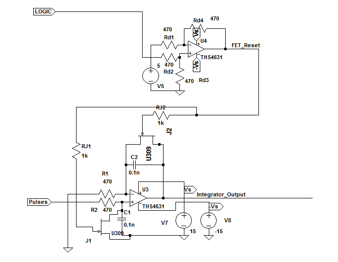
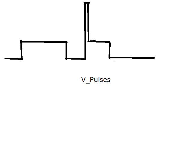
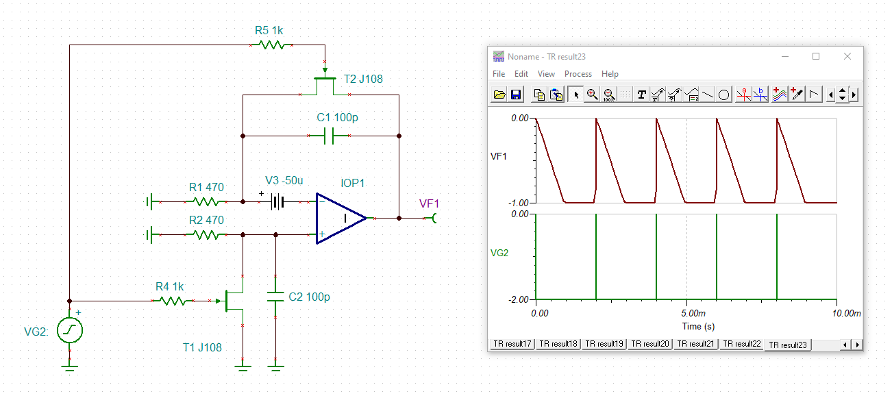
I have used THS4631 in an integrator circuit (for a current sensing application) shown in the image attached below. The circuit is used to integrate two successive pulses of different width (rough shapes drawn below), other very short but larger amplitude) as shown. Moreover, I also use two FETs to reset my integrator circuit capacitors to zero voltage after each pulse ends. The reset FETs are in turn driven by a voltage level shifting circuit which uses another THS4631 at the output as shown. Both these op-amps share the same supply voltage.
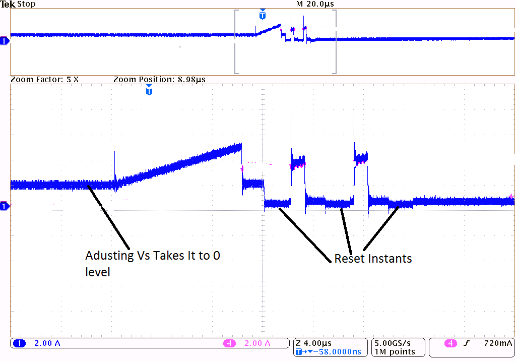
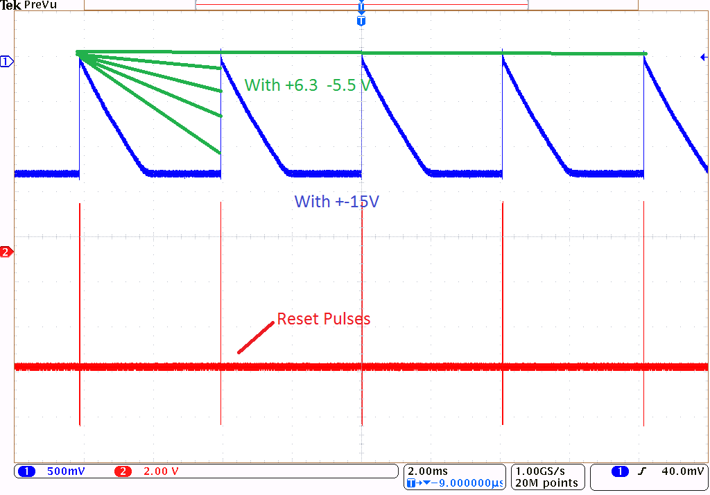
The problem I face is that I get the appropriate response only when I fine tune the supply voltage to +6.3V and -5.5V. This combination yields zero offset in my integrator circuit output. But if the supply voltage varies even slightly, there is a huge offset in the op-amp output. I have also attached an example of such offset. The offset continuously changes as the supply voltage is varied. I went through the device datasheet multiple times but still don't get why this is happening. The only clue was from the source and sinking current levels which depend on the supply voltage. But even then, I don't understand how it would translate to the observed offset. Is the same supply voltage feeding both the integrator op-amp as well as the rest driver an issue somehow? Is the op-amp offset voltage at play? Kindly help me unravel this as this manual adjustment of supply voltage isn't really a practical solution.
In place of U309 in the circuit shown, I have instead used PMBFJ109. The simulation works perfectly. No such offset is seen due to any variation in supply voltage there. The pink waveform is how it should be like (From direct current measurement). The blue one is the integrator output.