This thread has been locked.

If you have a related question, please click the "Ask a related question" button in the top right corner. The newly created question will be automatically linked to this question.

PGA308: Calibration on PGA308EVM Software

Genius 16365 points
Part Number: PGA308
Other Parts Discussed in Thread: , DRV5053

Hello,


Our customer is trying to evaluate PGA308 but is facing an issue.


They are trying to calibrate with PGA308EVM Software. Now Vin1 and Vin2 are input from external and VCLAMP, VS and Vref are 5.4V.

When Vin1=1.0V and Vin2=1.0V were input for offset(MIN) and Vin1=1.0V and Vin2=1.3 were input for Span(MAX) during the calibration, it was correctly configured within 1-5V range Vout.

But when Vin1=1.0V and Vin2=1.0V were input for offset(MIN) and Vin1=1.0V and Vin2=1.5 were input for Span(MAX) during the calibration, it was NOT correctly configured.

It looked like that Vout was saturated to 5V when Vdif(Vin2-Vin1) is over 0.4V in this case.

Also when Vdif was actually over 0.4V like 0.5V(Vin1=1.0V, Vin2=1.5V), the PGA308EVM software showed “Measured Full Scale” was 405.0m like the below figure.


Is it possible to input over 0.4V for Vdif on PGA308?

What do you think of the root cause of this issue?


Regards,.

Oba

  • Hi Oba,

    Per your description, it appears you are applying ext. differential input of Vdiff=500mV with VCM = 1.25V common-mode; Vin1=1.5 and Vin2=1.  This signal range is larger than a typical bridge sensor used with the OPA308.  For example, the sensor emulator built in the PGA308EVM provides a max range of +/-50mV, as shown in the simulation tab.

    Can you please show a  a detailed diagram showing the sensor connections and/or signal source connections to the PGA308, including the ground connections?

    What type of source signal or sensor are you using on this application?  If  a datasheet is available, please provide.

    Thank you and Regards,

    Luis

  • Hi Oba,

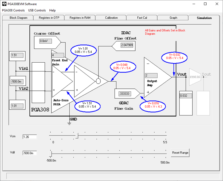
    Using the Simulation tab, if you extend the  range to Vdif =+/-0.5 and VCM = 1.5V, with VIN2=+1.5V and VIN1=+1V shows that the device is in range.  However if you reverse, VIN1 = 1.5V and VIN2=1V; the PGA will be outside of range.  Below is an example where the device is outside of range if VIN1 and VIN2 are reversed.

    Please post a detailed diagram showing the sensor connections and/or signal source connections to the PGA308, including the ground connections; and the sensor, circuit or component that is generating the input signal.  In general, the calibration routine is optimized for small signal ranges, and there are cases that could be outside the PGA308 calibration range; but will investigate this in detail on the PGA308EVM after I receive your diagram, 

    Thank you and Regards,

    Luis

  • Hello Luis,

    Thanks for your reply.
    The input voltage, VIN1 and VIN2, actually doesn't come from any sensors.
    They just use an external voltage source like stabilized power supply for these VIN1/2 just to test PGA308 operation.

    I'm not still sure how they finally want to connect to, but they will want to connect DRV5053 to PGA308.

    Regards,
    Oba

  • HI Oba,

    The PGA308 is a bridge sensor conditioner, intended for strain, load and weight scale sensors, and its calibration routine and internal DAC voltage ranges are intended for small differential signals. Depending on the offset DAC and Gain settings used, you could be outside the linear range of the amplifier stage.

    Section 3.1 Gain Scaling and Figure 3-2 on the PGA308 User Guide describe the equations to perform the internal node calculations and the equations that limit the valid range of the device.

    In general, Customers use the bridge sensor emulator built into the EVM (signals generated by the USB DAQ board DACs) to test the device, or alternatively, an external bridge sensor emulator, as the one shown below. The calibration procedure consists in applying the min signal voltage on the bridge and max scale condition to perform the gain and offset calibration.

    http://www.ti.com/tool/SENSOREMULATOREVM

    In general  bridge produces a differential output signal, and the common-mode voltage of the bridge sensor signal remains at a constant common-mode, and a differential signal at a fixed common-mode is produced as the weigh changes. In your case, the common-mode voltage is changing which is different from a bridge sensor.

    The DRV508 produces a single-ended output signal, if you let us know what is the expected amplitude range signals out of the hall sensor in this application, common-mode voltage and frequency, (or if you explain how they plan to connect the single ended sensor), we may suggest a different instrumentation amplifier or a different circuit.

    Thank you and Regards,

    Luis