This thread has been locked.

If you have a related question, please click the "Ask a related question" button in the top right corner. The newly created question will be automatically linked to this question.

OPA627: Perfect circuit for OPA627 and OPA134

Part Number: OPA627
Other Parts Discussed in Thread: OPA134, TPA6120A2, OPA828

Hello,
I would like to use the OPA627 and the OPA134 in optimal wiring (non inverting) in front of a TPA6120A2.

Unfortunately, despite an intensive search, I did not find any information about the configuration or circuitry used for the OPA 627 and OPA134 to achieve the optimum result from low noise and good stability.
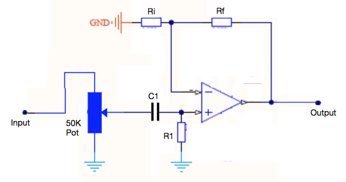
In front of the OPA is a 50k potentiometer and a coupling capacitor (1uF KP or 40uF / 80V bipolar electrolyte), as shown in the diagram.
At the output comes a TPA6120A2 as shown in the data sheet under 10.2.1.2.1 (with the 50R resistor between OPA and TPA6120A2).

In the current circuit, all 3 resistors have a value of 10k.
A gain of 1-3 would be enough.
The supply is +/- 15V.
The circuit is to be operated at the outputs of conventional audio devices (DAC, s, CD player).

With which wiring would an OPA627 and OPA134 (the wiring for both OPA do not have to be the same) achieve the best performance from lowest noise and best stability under these conditions.
Is R1 needed? Or does a resistance to ground have to be inserted before C1?

Thank you in advance for the help
Roland

  • Hi Roland,

    have you worked through this FAQ?

    And this site is a real gold mine:

    Kai

  • Hello Roland,

    Kai has directed you to some very good resources that cover various subjects on the application of high performance audio op amps. I recommend looking over them to see if they provide answers to you questions. If not, let us know and we will help you find answers to your questions.

    The OPA627 and OPA134 are both low noise, high performance audio op amps. The OPA627 1 kHz noise is rated at 5.6 nV/√Hz typical, while the OPA134 is rated at 8 nV/√Hz typical. You have to be careful with the resistor values you select to place around the op amps. If they are too high in value their thermal noise will exceed the voltage noise of the op amps, and degrade the overall noise performance of the amplifier stage. You mention using 10 kilohm resistors for the three resistors. I would reduce them by a factor of 10x, or as much as possible to minimize their thermal noise contributions. That also goes for the potentiometer as well, but it is shunted by R1 and the thermal noise in that path will be the parallel combination of R1 and the potentiometer. I suggest having a look at TI Precision Labs - Op amps, Noise for more information about noise concerns and minimizing it:

    https://training.ti.com/ti-precision-labs-op-amps-noise-1

    Regarding the stability issue, there isn't anything about the circuit you have shown that would trigger a stability concern. Instability most often occurs due to degradation of the amplifier circuit's phase margin; when the phase through the op amp and around its feedback loop become 360° (0°) and the circuit becomes an oscillator. This most often occurs when the op amp has a capacitive load on its output, and/or capacitance from its summing node (inverting input) to ground. This is a vast subject in itself and again covered at length in TI's Precision Labs - Op amps series:

    https://training.ti.com/ti-precision-labs-op-amps-stability-1

    Note that the OPA627 and OPA134 JFET op amps are both legacy op amps, and although still active there are newer devices you may want to consider. The OPA627 has new counterpart OPA828:

    http://www.ti.com/product/OPA828

    It boosts even lower noise than the OPA627. For the OPA134 I suggest having a look at TI's audio op amps which includes a number of JFET input devices:

    http://www.ti.com/amplifier-circuit/op-amps/audio/products.html

    Regards, Thomas

    Precision Amplifiers Applications Engineering