This thread has been locked.

If you have a related question, please click the "Ask a related question" button in the top right corner. The newly created question will be automatically linked to this question.

LMC6024: LMC6024 Fails to Start - Stuck Low

Part Number: LMC6024
Other Parts Discussed in Thread: TLV274

Hello,

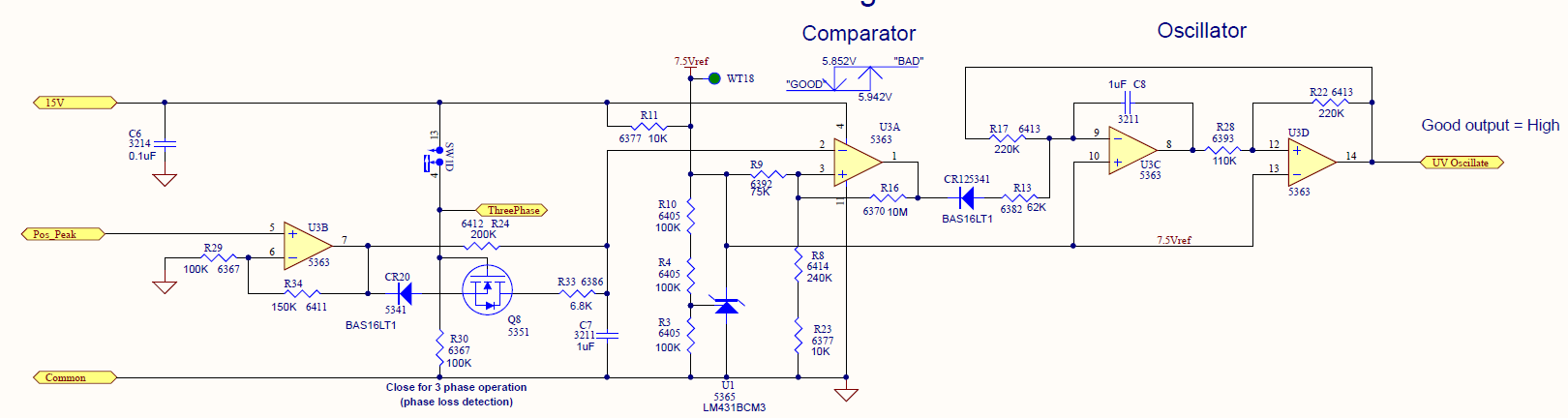
My company has a design using the LMC6024 quad amplifier, powered V- = 0V, V+ = 14.5V.  It has worked great for a number of years, however lately our newer boards have been having problems.  Sometimes when these boards power up the first op-amp stage (non-inverting) will have an output that remains at 0V regardless of the voltage on the non-inverting input.  The only way to get the op-amp working again is to power cycle the entire board.  I've tried swapping op-amps from older boards to newer boards and this problem only seems to track to the new op-amps.  Does anyone have any suggestions or has anyone seen this same behavior?

  • Hello Paul.

    Can you measure the voltage at both supply pins and all the pins of the op amp channel?

    Please show or describe in detail the setup for the amplifier stage.

  • Hi Ronald,

    When the circuit doesn't start up as expected I see the following voltages:

    V+ (Pin 4) = 14.851V

    V- (Pin 11) = 0V

    In+ (Pin 5) = 5.06Vavg this signal oscillates between 2-6V 

    In- (Pin 6) = 0.15V

    Out (Pin 7) = 0V

    The schematic can be seen below.  The first amp on the left is where I am seeing this problem. 

  • Hi Ronald,

    When the circuit doesn't start up as expected, the voltages are:

    V+ (Pin 4) = 14.85V

    V- (Pin 11) = 0V

    In+ (Pin 5) = 5.06Vavg - this signal oscillates between 2V and 6V

    In- (Pin 6) = 0.15V

    Out (Pin 7) = 0V

    The schematic can be seen below.  The first amp on the left is where I see this issue.  

  • Hi Paul,

    it sounds like that you suffer from latch-up. Latch-up can occur when you violate the absolute maximum ratings, even briefly. Specifically, the input and output pins must never be driven beyond the supply rails by more than 0.3V.

    Can you show a schematic?

    Kai

  • Paul,

    I also suspect that pin 5 voltage may exceed the power rails momentarily. Pin 6 is interesting because it appear to be a 2.5uA source. What generates the Pos Peak input. Can it provide high current?

  • Happy Easter Paul!

    Not knowing more about your circuit, I would recommend the following modifications:

    I would clamp the input voltage to the rails by the help of BAV99. But this clamping only makes sense, if the supply voltage of LMC6024 cannot rise above 15.5V. So, the input signal should come from a circuit which is also powered by +15V.

    An additional current limiting resistor is inserted between this clamp and the input of LMC6024. Assuming a voltage drop of less than 1V across this 220R resistor gives a maximum current of less than 5mA into the input pin of LMC6024.

    There's another issue in your circuit. If the supply voltage can suddenly drop down to 0V, U3A and U3C are in danger. Then, the according 1µF caps also suddenly discharge through the ESD cells of LMC6024 at the input and for U3C also at the output. I have sketched the situation for U3C:

    This results in a current through the ESD cells which will exceed the absolute maximum ratings. A diode clamp and an additional current limiting resistor can also help in this situation.

    This protection is useful, if the +15V supply voltage goes down faster than about 220k x 1µF = 0.22s

    Kai

  • Hi Kai and Robert,

    Thank you for the feedback and suggestions.  I will give this a try today. 

    The 15V is generated from a 15V Zener (BZX84C15).  The entire board is being powered from 480Y/277 3-phase.

    Here is a schematic capture showing the 15V supply and the input (Pos Peak) of the amp of U3B.

    Only SW1B (opamp page) and SW1D (from the Peak Detects page) are closed. 

    Thank you both again for your help!

  • Hi Kai,

    Just wanted to give you a quick update.  I added the BAV99 parts and 220 ohm resistors to my circuit, but I do still see 0V stuck on my output occasionally after power up.  

    I'm looking at alternate opamps I am going to try to see if they behave more consistently. 

  • Hi Paul,

    how big is Rx?

    Is C14 a Y-cap? Hhm, it's a bit small.

    The switching will contaminate signal ground ("Common"). Do you use a star-connected signal ground wiring in your setup?

    Kai

  • And some scope plots would be helpful, as already mentioned by Ron.

    Kai

  • Hi Kai,

    Thanks for the feedback.  The current schematic has nothing for resistance where you drew in Rx.  I threw in a 100K there for testing. 

    Yes, C14 is an AC line rated disc capacitor part number VY2470K29U2JS6

    The grounding path could certainly be cleaned up.  As you can see from the PCB screenshot below it looks like no special attention was given to grounding and there are several unnecessary ground loops. 

    I'll be in the office again tomorrow so I will try to capture some scope captures to share. 

  • Hi Paul,

    Rx = 100k is a good choice for the testing.

    The white wires are signal ground ("Common"), as you wrote. My question, and it is an important one, is: Does the printed circuit board provide a solid ground plane?

    Kai

  • Hi Kai,

    No ground plane at all - only the signal ground highlighted in white. 

  • Paul,

    When U3B is stuck, does U3A work correctly That would be U3A output high. Pulling IN- of U3A high should make U3A output low to prove it is working and not just stuck high (opposite of U3B).

  • Hi Ronald,

    No, U3A output (pin 1) is also low.  As soon as I pull IN- of U3A (pin 2) up to the 14.5V rail everything starts working again. 

  • Hi Paul,

    oops! Not having a ground plane is really bad. This can be the cause of trouble.

    Some switchings within the circit can generate inductive kick backs on the snaky and inductive ground traces. This can shift the ground potential and cause latch-up.

    Kai

  • I appreciate all the help.

    This board is 15-20 years old and is in dire need of a redesign anyway.  

    We've never had problems with this part until this year so I'm convinced there must have been was a process change.

    In any case, in the short term, I think we will use TLV274 from TI as a replacement. 


  • Hi Paul,

    if a design is running on the edge (I don't know the exact term in English :-)), only a very little change is enough to make the design suddenly fail. This doesn't need to have to do with the LMC6024 itself. It can also be the result of a design change of some of the many MOSFETs you use or even slight changes of the passive components. So, at this moment I'm not quite sure that the LMC6024 is the wrongdoer. But, of course, may the TLV274 solve the issue!

    Good luck :-)

    Kai

  • Paul,

    Do you have results from the TLV274 testing?

  • Hi Ron,

    We have replaced the part on several boards with the TLV274 part and have had no further issues.

    Just as an FYI, as a test we took several of our new problematic boards and several old working boards and swapped the LMC6024 part between these boards.  The problem followed the part around.  The old boards with the newer part began failing and the newer boards with the older part began working 100%. 

    Best Regards, 

  • Hi Paul,

    could the bad parts have become damaged by ESD or else during the shipping, handling or mounting? Or a damage during operation? Very strange...

    Kai

  • Kai,

    I don't believe so.  I ordered more LMC6024 parts from Digikey and noticed the same behavior.  The only thing I can think of is this may be related to a recent PCN of the part.  There is a PNC #20190506000.1 dated May 15th 2019 (Aug 15, 2019 proposed 1st ship date) for assembly process and material changes. 

    In any case, the other TI part that we switched to is working fine and will probably be our solution for future production. 

  • Paul,

    I also order digikey samples and tried to "lock up" the op amp with negative input or output current (upto 20mA) during power up. I wasn't able to get a lock up state. In any case, a different op amp is a good solution as it is a completely different design and lock up would be very design specific.