This thread has been locked.

If you have a related question, please click the "Ask a related question" button in the top right corner. The newly created question will be automatically linked to this question.

ISO224: Power supply for isolated amplifier

Part Number: ISO224
Other Parts Discussed in Thread: ISO124, AMC1311

Hello

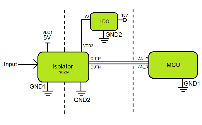
  I need to measure a voltage, block diagram is :    
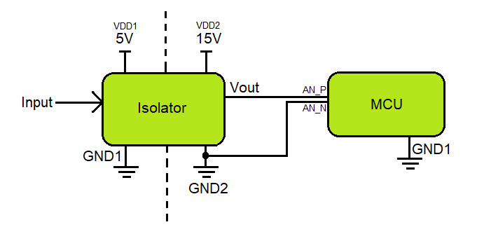
                  

    the thing is that ISO224 has max VDD1 26V and max VDD2 6.5V, and I need the opposite, is there some isolated amplifier with these specs?


  • I am sensing only positive voltages, in that sense, if I use ISO124 with +VS1=5V, -VS1=0V (tied to GND1); +VS2=15V, -VS2=0V (tied to GND2), is it feasible ?,  

  • Hi Fausto,

    the ISO124 needs a minimum supply voltage of +/-4.5V at both sides.

    Kai

  • Hi Fausto,

    ISO124 requires bipolar power supplies for specified operation, a minimum of +/-4.5V as Kai pointed out. 

    Unless you need the extended creepage/clearance that the ISO124 provides, I would not recommend it over the ISO224. 

    Unfortunately we do not have an isolated amplifier that meets your exact specs. 

    The ISO224 can operate with a minimum of 4.5V unipolar supplies on both sides, with a max of 5.5V on the low side. Is using an LDO to drop from 15V to 5V a possibility for your application? 

    Furthermore, the output of the ISO224 is differential, not single-ended as shown in your block diagram. For high performance, direct connection to a differential ADC or doing a differential to single-ended conversion with an opamp is best. For lower cost, simply use the positive output connected to the MCU and terminate the negative output to GND through a weak (10k) resistor.   

  • My mistake, I fixed the issue about ISO224 differential output and the LDO, so,  something like this:

            MCU power supply rail is the same of the system from where the input is taken - left side--, the idea is just to avoid any some possible influence/disturbance of the measurement sampling in the system.

  • I may be mis-understanding, but is the MCU and ISO224 power rail going across some sort of isolation such as an isolated transformer? Otherwise the MCU will not be protected from the high voltage side of the circuit. 

    What type of measurement is on the input? AC or DC? Voltage or Current sensing and what magnitude? 


  • It is DC voltage from 10 to 40 Volts,  I just want to avoid any current flow from the system  when measuring.

  • Hi Fausto,

    I'm a bit confused too. Can you tell a bit more about your application?

    Kai

  • Hi Fausto,

    In that case I would recommend AMC1311 over the ISO224.

    However I am not certain that you need an isolation amplifier for this use case since you will only be measuring up to 40V.   

    As Kai said, can you provide more information about this application? 

    Is isolation required for your measurement? 

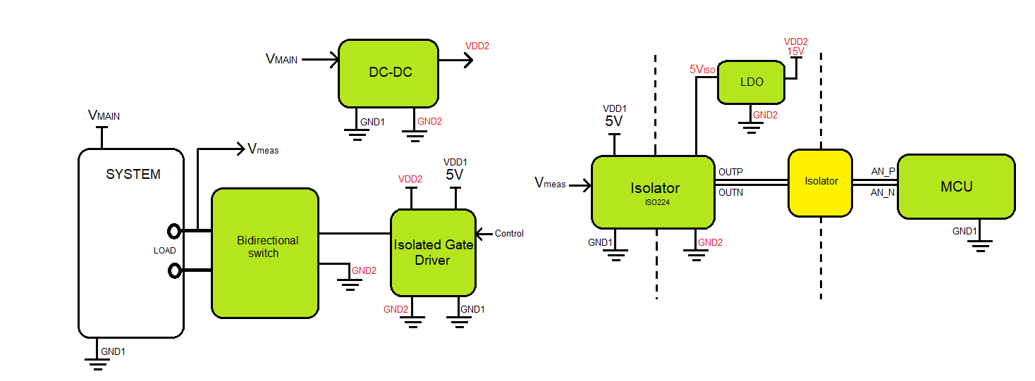
  • Hello Kai/Alex, here is a more complete block diagram:


        I would need another isolator (yellow) to have a complete isolation, but not sure if there is a differential input isolator or I should do some kind of adaptation with a ISO224.

    Isolation is required as I do want to have any kind of disturbance in the system under test.

  • Hi Fausto,

    Do you have the power supplies swapped for the Isolated Gate Driver block? I would expect to see VDD1 on the left and VDD2 on the right, same as the ISO224. 

    If using an additional isolator, you would want to use a modulator, not an amplifier like the ISO224 since you would need an analog to differential conversion. 

    Are you trying to meet an end equipment specification that requires double isolation in the measurement path? 

    What is the magnitude of Vmain? 

  • Hi Fausto,

    Just checking in here. 

  • Hello again

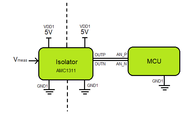
       I think what I need is just this 

    I just want to avoid completely any impact on Vmeas point (current drain).

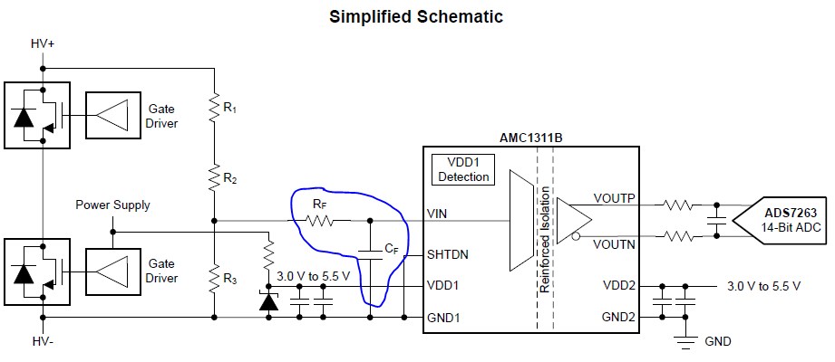
    I just have one more question, I see an input filter:

      Is there some recommendation for values?

  • Ciao Fausto,

    with a total source resistance of 114k, including R1, R2, R3 and RF, the typical offset voltage error caused by the typical input bias current equals the typical input offset voltage error:

    114k = 0.4mV / 3.5nA

    So, I would recommend a total source resistance of less than 100k.

    The total source resistance is:

    (( R1 + R2 ) // R3 ) + RF

    "//" means "parallel resistance".

    Kai

  • Oops, I forgot CF.

    As the delta-sigma moduIator is running at 20MHz, I would choose a corner frequency "fc" of less than 275kHz for the AMC1311B:

    fc = 1 / (2 x pi x RS x CF)

    With Rs is the total source resistance calculated in the post above.

    Of course, choosing a much lower corner frequency is possible and recommended, if the application allows.

    Kai

  • Hello Kai

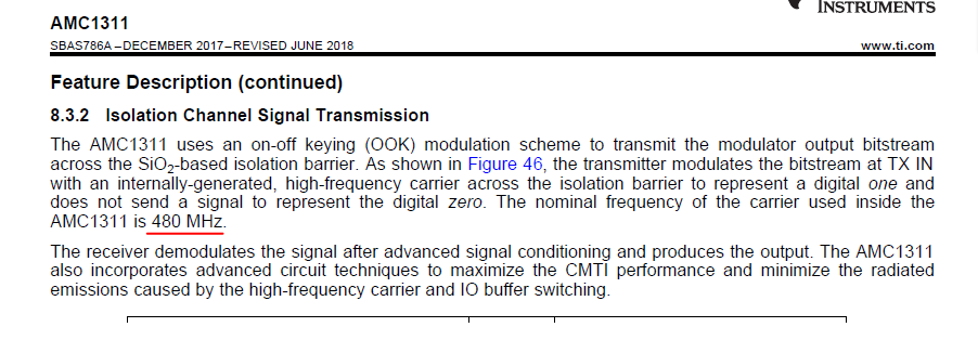
      Looking in the datasheet I see :

       is not 480Mhz ?

    br

  • Hi Fausto,

    As Kai said, the modulator frequency is 20MHz. The clock used transfer the data across the isolation is 480MHz. 

    General rule of thumb is to set the cutoff frequency of the anti-aliasing filter at least one decade below the modulator frequency, which would be 2MHz in this case. A more aggressive cutoff frequency such as 275kHz is perfectly acceptable depending on what frequency the signal of interest is and what type of noise content is in the system. If using a low input impedance device, I recommend keeping the R value low (10ohm) to minimize the error created by the input bias current.  If using a high input impedance device such as ISO224, this is not as important since the input bias current will be much lower. 

    Thank you Kai!