This thread has been locked.

If you have a related question, please click the "Ask a related question" button in the top right corner. The newly created question will be automatically linked to this question.

LMP7721MAEVALMF_NOPB: Simplified Trans-impedance with "Tee" Feedback

Part Number: LMP7721MAEVALMF_NOPB

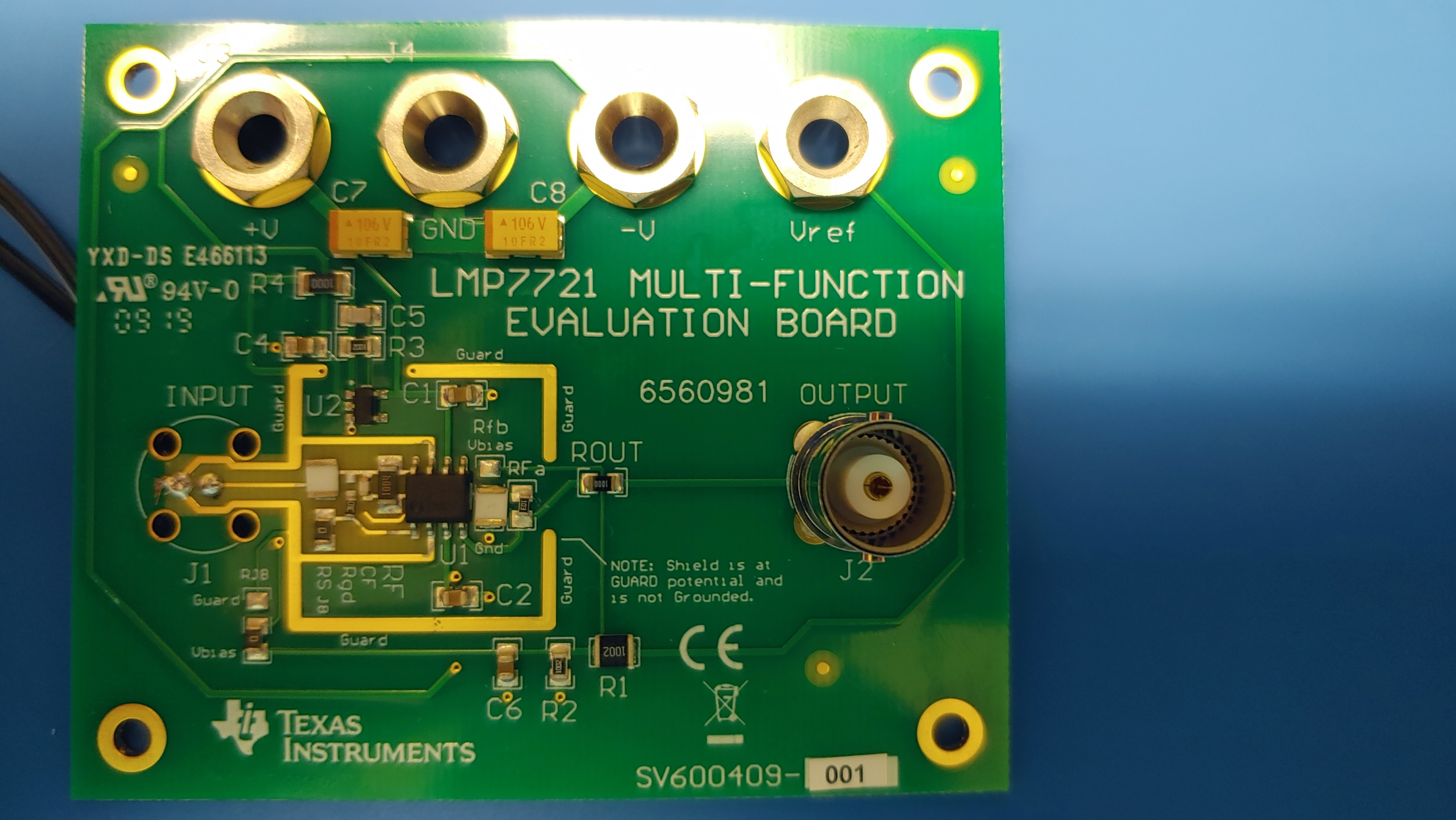
I have a LMP7721 evaluation board that I am trying to put into a transimpedance amplifier mode. I am trying to measure the leakage current of capacitors. When I test the LMP7721 evaluation board with a 1G resistor at 1V the output of the LMP7721 will either rail or oscillate at 60Hz. Does anyone have any advice as to what I am doing wrong? I have attached a photo of how I changed the evaluation board, and a schematic I have been using.DOC_2000010100004400085_001.pdf

  • Hi Allan,

    where do I see the 1G resistor in the photo?

    Kai

  • HI Allan,

    Some common problems encountered with ultra low input bias current, very high gain transimpedance amplifier applications are:

    1. Random leakage currents due to inadequate PC board cleaning. Solder flux residue, or finger oils on the board provide unexpected resistive paths for leakage current flow. The leakage currents can exceed the current to be measured and the output voltage rails due to the very high transimpedance gain. We recommend using solder with water soluble flux and then ultrasonic cleaning the boards with DI water followed by a forced air drying cycle. This is cycle is accomplished twice for best results. Sometimes the flux residue gets under the surface mount components and is difficult to remove by any means except ultrasonic cleaning.
    2. Fifty or 60 cycle oscillation is often cited as a problem, but in reality it is 50 or 60 Hz power line fields being coupled into the very high transimpedance circuit that is really the issue at work. Whenever working with these circuits in the lab we enclose the circuit in a shielded metal enclosure. Any input and output lines are shielded, and the power is often applied from batteries housed inside the enclosure with the PC board. Otherwise, the power supply lines leading into the enclosure must be bypassed to the enclosure using bypass capacitors at the entry points. The bypass capacitors need to be effective at both 50/60 Hz and the usable frequency range of the transimpedance circuit.

    Give these ideas thought and see if they may apply to your LMP7721 circuit installation.

    Regards, Thomas

    Precision Amplifiers Applications Engineering

  • Thomas,

    Thank you for the suggestions. I will try to implement them. Since I am trying to measure the insulation resistance of capacitors connecting a high voltage power supply seems to damage the LMP7721. By connecting the TIA like so do you think the op amplifier is damaged by exceeding the differential input voltage or something else?

    Thanks,

    Allan

  • Hi Allan,

    Oh! The LMP7721 uses a low voltage semiconductor process and it has a maximum rated supply voltage of 5.5 V. The input stage has back-to-back clamping diodes and current limit resistor to protect it under normal usage conditions. You can see a simplified input structure below as presented in the datasheet. If too large of a differential input voltage is placed across the inputs there is the possibility of damaging the input clamp diodes or some cases ESD diodes.

    The LMP7721 Maximum Voltage on Input/Output Pins is specified as (V+) + 0.3 to ( V−) − 0.3 V, and there is Note 3 by the Maximum Supply Voltage specification that states, "(3) The voltage on any pin should not exceed 6V relative to any other pins." That would apply to the input pins as well. If your test circuit is allowing a situation where the differential voltage, or applied voltage exceeds the limits it could result in damage to the LMP7721.

    Unfortunately, because of the ultra-low input current nature of the LMP7721 it would be nearly impossible to add over-voltage protection around it without drastically changing the input bias current performance. Protection components simply have too much leakage current to be useful in this kind of application.

    Regards, Thomas

    Precision Amplifiers Applications Engineering