This thread has been locked.

If you have a related question, please click the "Ask a related question" button in the top right corner. The newly created question will be automatically linked to this question.

OPA549: PCI analog card damaged in an op amp circuit

Part Number: OPA549

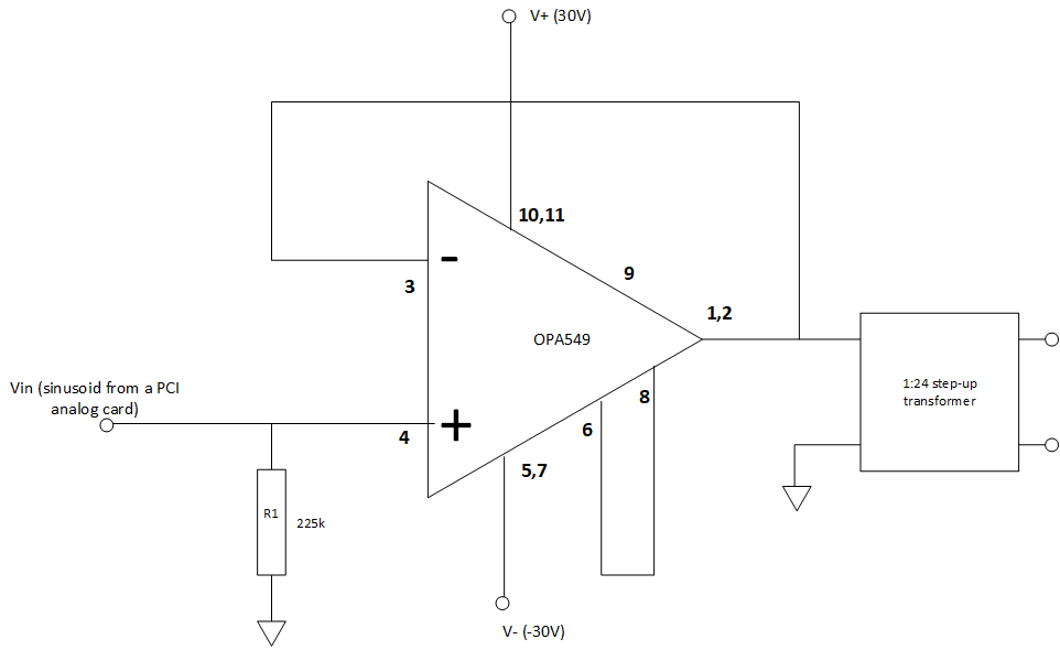
I am using an OPA549 and a 1:24 transformer to step up a sinusoidal signal from a PCI analog output card for a HIL testing.

It worked fine for a while; but recently the PCI analog output card was damaged. On observing the physical card, we suspect some return currents might have flown into the card from the op-amp circuit. Did I miss anything important in the grounding/referencing in the circuit below?

  • Hello Sriman,

    The OPA549 is capable of delivering high levels of current up to 10 amperes peak to a load. If for some reason the load under some set of conditions looks like a low impedance the OPA549 will deliver high output current. Since it is the PCI card that is being damaged and not the OPA549 it does appear that the card under some voltage or current condition is susceptible of becoming damaged.

    The OPA549 is driving the 1:24 step-up transformer in the circuit you show so the voltage at the secondary can be very high. If for example the OPA549 output voltage gets up to 25 V peak, then the secondary voltage is 600 V peak. If the PCI card isn't designed to handle such a high voltage damage would likely occur.

    If you can provide more information about your OPA549 circuit and the PCI card that would give us something more to examine with regard to the damage that is occurring.

    Regards, Thomas

    Precision Amplifiers Applications Engineering

  • Hello Thomas, 

    The PCI card is an analog output card that is being used to provide the low level input signal to the op amp [+/-15Vpeak]. The output of the transformer secondary is not loaded. The OPA549 circuit is just a simple voltage follower with the input coming from the PCI card as shown in the picture above. The PCI card is a DAC module: https://www.opal-rt.com/wp-content/uploads/2016/07/OP5330_User_Manual.pdf

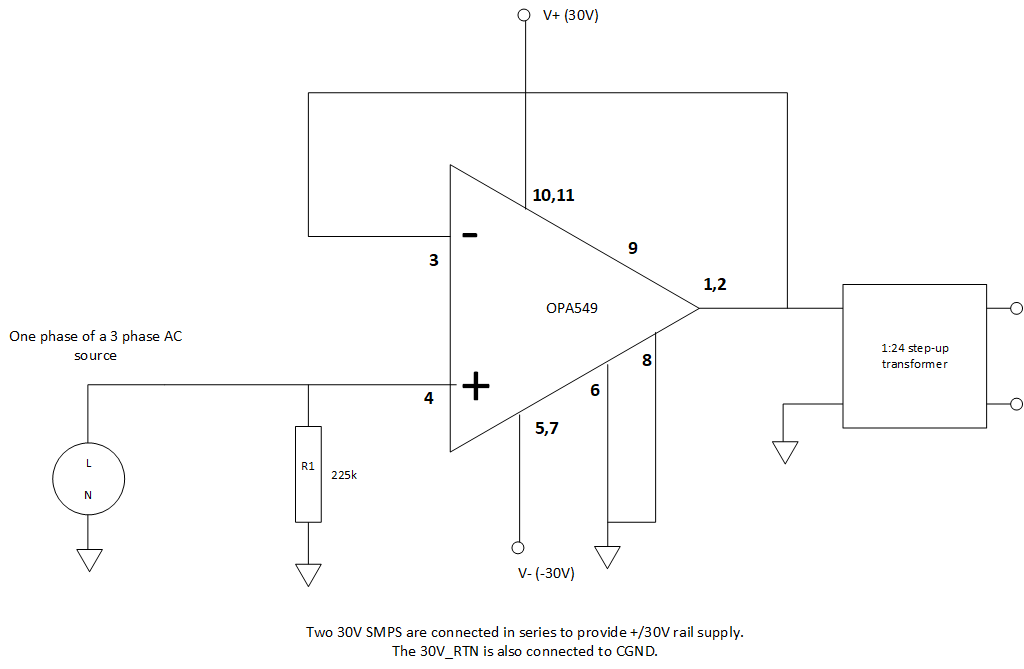
    An update: To avoid damaging another AO card, we tried to recreate the setup, now with an AC power supply instead of the AO card at the input. This has damaged the OPA549 now. There was no load on the transformer secondary in this case as well. The damage seems to be around pin 5,6 and 7.  

    The schematic for the circuit with the power supply is similar to the AO circuit. 

  • Hello Sriman,

    Thanks for your  update: "To avoid damaging another AO card, we tried to recreate the setup, now with an AC power supply instead of the AO card at the input. This has damaged the OPA549 now. There was no load on the transformer secondary in this case as well. The damage seems to be around pin 5,6 and 7."

    An unloaded transformer will exhibit a complex load impedance that is a function of frequency. Generally, at low frequencies it will behave as an inductive load. The transformer winding resistance will be in series with the inductance. The problem with a load of this nature is that it is not well defined and depending on the output being provided to the transformer by the OPA549 output it is possible to end up with a back EMF condition. The back EMF may try to force current back into the OPA549 output and the voltage resulting from the EMF can rise to a level where it exceeds the supply voltage.

    It is always advisable when the load has significant inductive reactance to include output protection for the power op amp output transistors. The OPA549 datasheet discusses this in Applications Output Protection section and shows how output protection diodes are applied in a motor drive application (Fig. 10). The information is a bit dated and we now recommend a protection circuit that provides more complete portection.

    The very fast silicon diodes and TVS diodes need to be able to handle the maximum OPA549 output current so plan for at least 10 ampere capability. I highly recommend that they be added to the circuit to protect the OPA549 output from back EMF events.

    Regards, Thomas

    Precision Amplifiers Applications Engineering

  • Hello Thomas, 

    Thanks for the reply. Could this be the reason even for the PCI card damage or do you suspect anything else? 

    Sriman

  • Hi Sriman,

    The OPA549 has ESD diodes that connect from the output pin to each of the supply pins. They are in place to protect against out of circuit handling ESD events. They are normally turned off during normal OPA549 circuit operation. However, during a back EMF event one or the other diode can be turned on and conduct. If that happens the power supply line can rise beyond its normal level and anything connected to that line will be exposed to that high voltage. If your PCI card uses that supply, then that to could be affected.

    Additionally, the OPA549 is one monolithic silicon die. If it becomes severely damaged due to an electrical overstress such as a back EMF, more than just the output transistors mays be damaged on the die. It seems conceivable that a damaging voltage level might find its way back to the OPA549 input and the PCI card under such unusual conditions. 

    Regards, Thomas

    Precision Amplifiers Applications Engineering