This thread has been locked.

If you have a related question, please click the "Ask a related question" button in the top right corner. The newly created question will be automatically linked to this question.

Fully Differential vs Single ended for Differential ADCs

Other Parts Discussed in Thread: THS4531A, INA592, INA826, THS4531

Hello,

I have a differential signal which alternates between 0 to 5V and I want to measure it with an ADC

I have three choices to do it:
1- using two single-ended op-amps and a differential ADC. 
2- using a fully differential op-amp and a differential ADC. 
3- using a single-ended op-amp to change differential to single-ended  and single-ended ADC


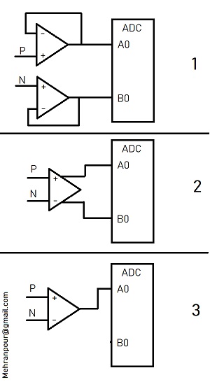
Which one is better?
I have to use an op-amp with a gain anyway since my ADC is 3.3V and the signal is 5V.
I would say the second configuration is the best but it is costly.
Regarding the common-mode rejection 2 and 3 removes that on the analog level but if I use two single-ended I will only rely on ADC common-mode rejection on the digital level.
I already check the application report of Texas Instrument about fully differential amplifiers so my questions arose from there.
Please help me in this regard Thanks in advance.

  • Hi Mehri,

    there's no simple answer. This depends on many things like speed, common mode noise, available resources, etc.

    Can you tell more about your differential signal? And what ADC do you plan to use (sampling rate, precision, digital interface, etc.)?

    Kai

  • Thank you Kai,

    It is a differential signal 5V
    we want to measure it with the ADC in ST F7 microcontroller which is 12bit.
    It will be in industrial fields.
    Since it will be in series production the price is important

  • Hi Mehri,

    Kai is asking the following application requirements. And I have some follow up questions. 

    1. How fast do the differential signals from 0-5V change or xV-5V, where x=1, 2, 3.. etc.?

    2. if you are using 12 bit at 3.3V, MCU has the resolution approx. 3.3V/4096=0.8 mV/bit --> is this adequate for your application? Or we can maximize the 12 bits' reference to improve ADC precision. 

    3. How is the ground signal conditioning in the application? Is it operating under high/Low noise, high/low current, magnetic field environment etc.? 

    4. What about operating temperature environment? (Temperature operating ranges from cold to hot in operation, and rate of temperature change in the operating environment).

    5. What is your digital interface in data transmission after ADC? --> similar to question in 3. How noisy is the digital/analog grounds.

    Once we have these information, we can suggest the best options for the application. We will consider the pricing for the application. 

    Best,

    Raymond

  • Well, if you don't drive diff in to a differnential in ADC, you at least loss a bit, but mainly you lose HD2, Look at the THS4531A

  • Thanks, Raymond,

    1- It is a torque sensor in a robot application. So it seems this has a resistor bridge.

    2- We have to use F7 microcontroller and I think no way to use 5V reference.

    3- It is in motor application we usually use star connection for the grounds but I would say it is in a noisy environment.

    4-Since the board is close to Drive motor also due to dense placement it works above 50 degrees TJ.

    5-We have UART and EtherCAT on the board.

    Regards,


  • Hi Mehri,

    the sensor providing the differential signal is a resistor bridge? Is it made of strain gauges? Are they forming a Wheatstone bridge?

    Kai

  • Hi Mehri,

    1- It is a torque sensor in a robot application. So it seems this has a resistor bridge.

    I still would like to know the differential voltage changes in the torque sensor. The torque sensor is likely configured as Wheatstone bridge, which it has very small changes in differential signals. Please take a look at INA826 or INA592. If the offset voltage is higher than your application in INA826, you may perform 2 points calibration in your ADC o remove the unwanted errors. INA826 and INA592 are low cost and high performance parts in 1ku per TI web prices. 

    I am assuming your have Wheatstone bridge sensor configuration. If you have to make the circuit with discrete op amp components, it may cost more in the end. 

    2- We have to use F7 microcontroller and I think no way to use 5V reference.

    I'd like to reduce the ADC's reference voltage less than 3.3V, if it is possible. Say if your output differential signal is less than 1.5V, you are not using other half of binary digits if ADC's reference is 3.3V. If you use ADC ref. voltage =1.5V, then you will fully utilize 12 bit  ADC possibility. Also, Michael mentioned that you may loss one bit resolution if your ADC is configured in a single ended approach. Please check with ST F7's datasheet. So I am recommending Image 1 from your image for the approach, if you want to have the best performance. 

    3- It is in motor application we usually use star connection for the grounds but I would say it is in a noisy environment.

    Since this is robot and motor application, you will not have a stable ground. Therefore, I am recommending to sample the signal differentially for the best performance, as described in part 1 and 2 above. If you have to sample single ended via ADC, it is recommended to keep the Common Ground trace between Op Amp and ADC as short as possible.  

    4-Since the board is close to Drive motor also due to dense placement it works above 50 degrees TJ.

    Both parts are rated for the temperature ranges.

    If you have any questions, please let us know. 

    Best,

    Raymond

  • Thanks, Raymond,

    I marked the post resolved by mistake, Sorry. :)

    The sensor has already built-in signal conditioning and it makes the unipolar Differential 5V with 2.5V offset.

    I did not understand the term "differential voltage changes in the torque sensor" What does it mean exactly?

    I had a misunderstanding regarding differential ADC inputs, I thought that they convert the analog signals to digital then they subtract them and give the output on the digital level. So If I understood correctly they have a good CMRR and they do common-mode rejection at the analog level in their inputs.

    So when do we really need a fully differential amplifier? In high-speed signals? and when we want to drive a bipolar differential signal with ADC?

    In a fully differential chip we would have some resistors in inputs so do you suggest having two voltage followers on inputs to improve the input impedance(like instrumentation amplifier)? or they should be designed so to match impedance in inputs?

    Regards,

  • The sensor has internal signal conditioning and provides a differential 5V

  • Hi Mehri,

    sorry, but it's impossible to give further help without knowing the sensor.

    Kai

  • Hi Mehri,

    Question:

    I did not understand the term "differential voltage changes in the torque sensor" What does it mean exactly?


    I am not certain what types of torque sensor you have, which is the Kai's question. 

    If the Torque sensor comes with a pre-configured package, you have to read the datasheet about  the sensor's output specification and requirements. If the torque sensor is using Wheatstone bridge configuration, its voltage input is a typical DC (can be AC as well) , which sometimes is called excitation voltage or DC biased voltage. Assume the dynamic torque response signals are a function of frequency, which are difference signals generated from Wheatstone bride in this example. This is differential voltage response, which is directly proportional to an applied force for a given distance. 

    I am guessing that you have an integrated torque sensor. Since I was not sure, I recommended both types of op amps. If you monitor the output of  your toque sensor, the DC biasing voltage is at 5V, your torque signals is riding on top of 5V (up and down). If this is what you had, you need to use INA592 part. 

    I still need to understand what types of torque sensors you have, since there are too many of different types of torque sensors on the market. Do you have a part number of the sensor?

    If your torque sensor is configured in an integrated package, and it has output of 5V --> it may be able to drive certain amount of output current, then your sensor may be able to connect directly to ADC (please check with the sensor's datasheet). 

    Question:

    I had a misunderstanding regarding differential ADC inputs, I thought that they convert the analog signals to digital then they subtract them and give the output on the digital level. So If I understood correctly they have a good CMRR and they do common-mode rejection at the analog level in their inputs. So when do we really need a fully differential amplifier? In high-speed signals? and when we want to drive a bipolar differential signal with ADC?

    An ADC with single-ended inputs is measuring voltage vs. ground reference.  A  differential ADC is measuring the input voltage difference between +IN and

    -IN at output of a differential op amp. Typically, it will require two ADC channels to make the differential analog measurement.

    At this point, I am speculating what sensor type you have. Your integrated torque sensor configuration has determined the type of op amp interfaces you are going to have. since you are not designing the sensor circuit from discrete component level. 

    Best,

    Raymond

  • Thanks a lot, Raymond

    The sensor is a reaction torque sensor and still is in the development stage so they can not provide more information.

    These changes in differential voltage can be considered in the slew rate of the chosen opamps or it is not enough?

    Best Regards,

  • Hi Mehri,

    can you at least accurately specify the signal of this torque sensor? A typical scope plot could help much.

    Kai

  • Hi Kai,

    So let's make it easy,  this sensor  (CS1210-A2) from TE is a good example the intended sensor will be like this.


    Best regards,

  • Hi Mehri,

    If CS1210-A2 is a representative your measuring application, I would recommend to keep fully differential measurement through out your data acquisition. The type of application is typically very noisy environment, differential signal changes are very small because sensor is requiring a large dynamic range. 

    Typically, instrumentation amplifier is used after torque sensor, see the wiring schematic in the datasheet. I will recommend Version -A2 in the datasheet to keep up CMRR in the measurement system. Typically the outer cable jacket is wrapped around with metal mesh to shield away from the unwanted EMI/EMC noises under the environment. 

    Best.

    Rau,pmd

  • Thanks, Raymond,

    I already started some simulations with THS4531.

    Thanks a lot for your support.

  • Hi Mehri,

    I'm sorry, but I do not see a differential output in the A2-version:

    Kai