This thread has been locked.

If you have a related question, please click the "Ask a related question" button in the top right corner. The newly created question will be automatically linked to this question.

LMP7731: LMP7731 - Cut off Frequency

Part Number: LMP7731
Other Parts Discussed in Thread: TINA-TI, THS4520, THS4551, THS4541

Hi Support Team, 

Am referring to one of the reference design with instrumentation amplifier. Which is configured as differential mode and with help of TI technical note i can calculate the Gain (https://e2e.ti.com/blogs_/b/analogwire/archive/2019/08/09/what-is-an-instrumentation-amplifier), 

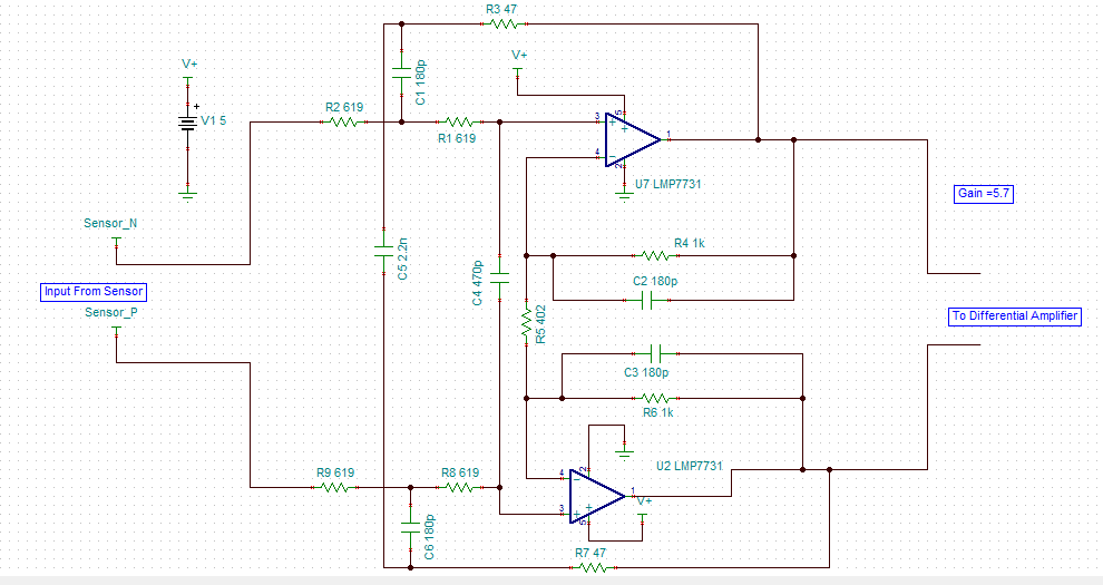
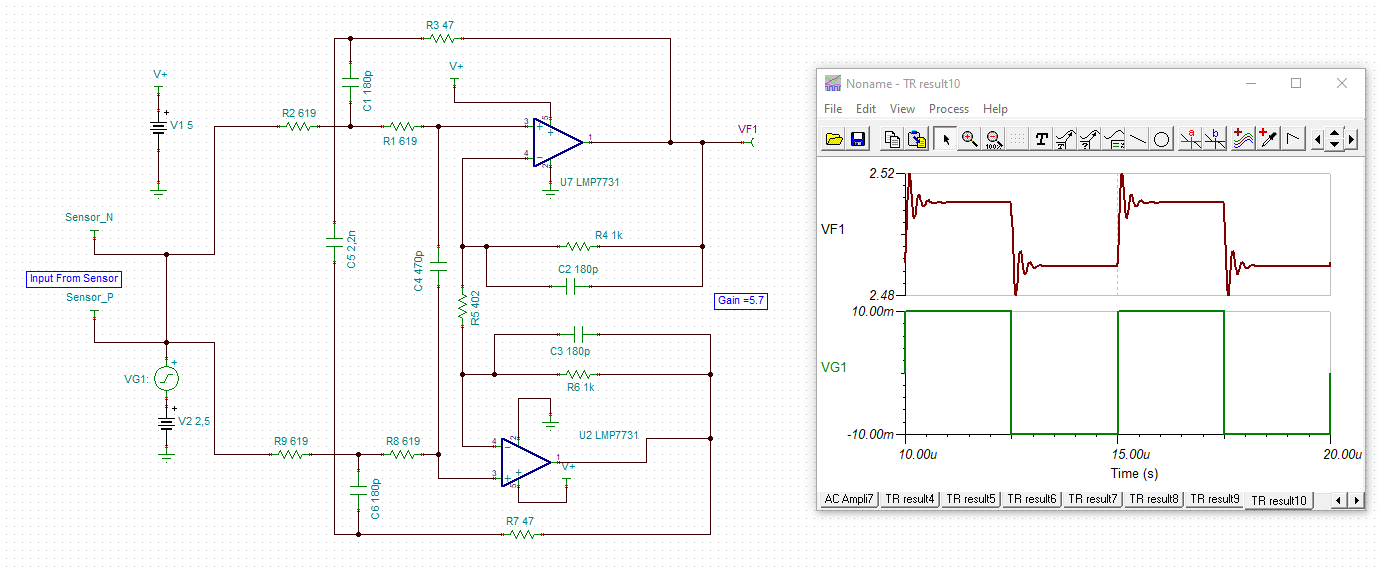
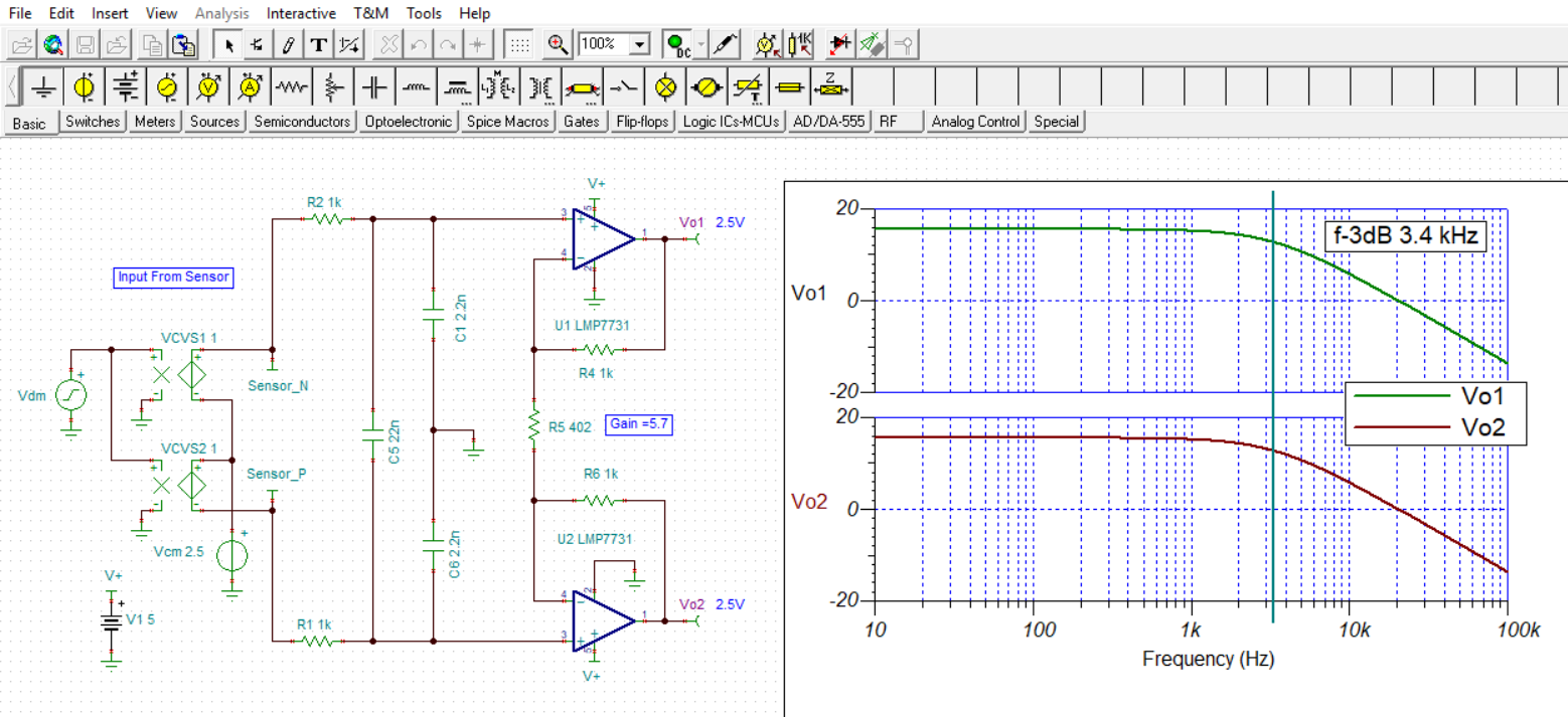
But am not sure about how to calculate cut off frequency with this configuration. Please refer to below image and i attached simulation file for your reference

It will be really helpful, if can support me on this. 

8780.LMP7731_Cut_Off_Frequency_Query.zip

  • Hi Balakrishnan,

    your circuit isn't very stable:

    balakrishnan_lmp7731.TSC

    Kai

  • Hello Balakrishnan,

    It seems the addition of the various capacitors to Brendan's original instrumentation amplifier application very much complicates the ac response of the circuit and results in less than optimum overshoot characteristics as Kai has pointed out. I am not sure what resource you referenced when applying the capacitors to this LMP7731 instrumentation amplifier (INA) implementation, but I think it is more complicated than it needs to be.

    The commonly used INA input filtering is shown in the slide below. The common-mode and differential filter cutoff frequencies are easily determined from the formulas in the slide. The differential mode capacitance is most often selected to be 10x that of the common mode capacitances. That has to do with the limited tolerance of the capacitors and minimizing the common-mode to differential mode signal conversion due to capacitor mismatch. The feedback capacitors can be added across the LMP7731 feedback resistors if you wish to bandwidth limit the op amps.

    I modified your original LMP7731 INA circuit to use the simple input filter like the one shown in the slides. I used a 22 nF differential capacitor as you did in your original circuit. The results for the differential response across frequency is shown below. The TINA-TI circuit is included for your use. You will find that this circuit does not exhibit the high overshoot characteristics of your original circuit.

    Regards, Thomas

    Precision Amplifiers Applications Engineering

    balakrishnan_lmp7731_02.TSC

  • Hi Thomas,

    Thank you for your detailed explanation.

    done few changes in my circuit, few more queries added and attached here the tina simulation file.

    I just understanding from reference schematic, Requirement to meet with 200KHz cut off freqeuncy and Q= 0.7.

    Cut off Frequency Query:
    I understood from your slide for INA differential mode cut off frequency calculation,
    But still am not able find the cut off frequency for my circuit.
    Cut off frequency depends on R1,R2,R3,R7,R8,R9,C1,C4,C5,C6.
    Can you help us to calculate cut off frequency with above parameter to match my requirement Fc =200KHz
    whereas measurement in tina Fc shows 262.92KHZ


    Phase Margin Query:
    1. If VCVS1 is connected to Sensor_N input pin:
    the phase margin measured at Vout_N 10KHz & 100KHz and which meets my requirement,

    2. VCVS2 supply connected to Sensor_P input Pin:
    But we are not seeing phase margin at Vout_P like point no 1

    3. If VCVS1 is connected to Sensor_P input pin:
    We are able to see the expected phase margin measurement,
    why VCVS2 supply is not helping to get a above measurement,
    Please eloberate on usage of power supply in this situation ?


    Transient Measurement:
    At FDA(THS4520) Output voltage swing from 0.25V to 4.75V, seems to be offset.
    Why is offset happening at output of FDA(THS4520), Swing should be 0 to 5V right ? 1K resistor value is used Feedback at FDA
    And there is no offset at LMP7731 output.

    It will be great if you have solution for my queries

    INA_LMP7731_to_TI.7z

    Bala

  • Hi Balakrishnan,

    you haven't changed the input filtering which is the cause of the common mode instability. You are using a circuit which is very exotic, so exotic that I have never seen it in an industrial circuit.

    I would remove the scheme arround R3 and R7 and go for the circuit Thomas has shown you. What common mode corner frequency and what differential mode corner frequency do you need?

    Kai 

  • Hello Bala,

    Note that I was not able to open your 7Z file. Regarding your question:

    "Cut off frequency depends on R1,R2,R3,R7,R8,R9,C1,C4,C5,C6. Can you help us to calculate cut off frequency with above parameter to match my requirement Fc =200KHz whereas measurement in tina Fc shows 262.92KHZ."

    The transfer function for your original circuit is extremely involved because of the many components and their interconnections. The circuit has both negative and positive feedback paths which further complicates the analysis. I do not see or find any reasonable way to to reduce the circuit to determine the various cutoff frequencies. I attempted to use the Symbolic analysis capability in the TINA Industrial version using ideal op amps it provided a transfer function that is hundreds of terms. As an example you can see below just the first page of the TINA analysis and several more pages are involved. Therefore, determining where the significant poles and zeros occur becomes a long and very involved project which is beyond the scope and purpose of the e2e forum.

    When I go through the circuit and estimate the various pole frequencies it appears that the 262.9 kHz cutoff, which appears to be the lowest cutoff frequency produced by any of the circuit's poles, it looks like it is coming from R1, R8, and C4:

    f = 1 / [2pi x (R1 + R8) x C4] = 1 / [6.28 x (619 + 619) x 470e-12] = 273.5 kHz

    Changing C4 to 642 pF should bring that pole down closer to 200 kHz. Below, I show the simulation results of changing C4 to 600 pF. The -3 dB cutoff frequency moves down to 200.8 kHz, and the ~1 dB of peaking is gone. I suspect the positive feedback being provided by R3 and R7 is introducing the peaking. However, there is a lot of interaction between the circuit elements and other changing component values will alter the amount of peaking as C4 does.

    If I were designing a circuit that required differential-in/ differential-out or differential-in/ single-ended out output, I would apply a 2nd-order differential active filter. The active filter topology would allow a precise filter response such as a Butterworth response to be specified from the onset. TI's Filter Designer Tool supports a Multiple-Feedback (MFB) differential active filter that can be set up for the required gain, cutoff frequency and Butterworth response. Additionally, see the following TI Analog Applications Journal for more about differential active filters.

    http://www.ti.com/lit/an/slyt343/slyt343.pdf

    Note that the wide bandwidth differential op amps are supported by TI's High Speed Amplifiers product group. They would be able to assist you with any questions about those op amps such as the THS4520.

    Regards, Thomas

    Precision Amplifiers Applications Engineering

  • Incidentally, if you are looking at higher speed FDA's , which you might if an active filter is in your future, the THS4520 is quite old and has poor DC precision - look at the newer THS4551 or THS4541. 

  • Hi Balakrishnan,

    We haven't heard from you in a while. We hope the issue was resolved. I am going to close this thread now. Please reply to re-open if you have any questions.