This thread has been locked.

If you have a related question, please click the "Ask a related question" button in the top right corner. The newly created question will be automatically linked to this question.

INA240: Common mode protection

Part Number: INA240
Other Parts Discussed in Thread: STRIKE, TMCS1100, TMCS1101, TIDA-00778, INA303

Hi,

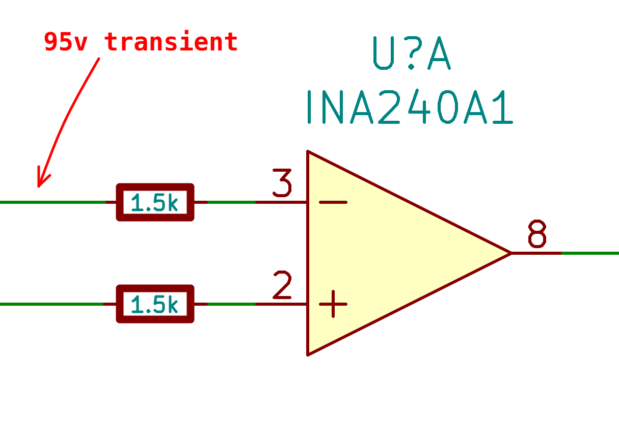
in this particular post it has been said that if the protection circuit can limit the current of those pins (IN+, IN-) to 5mA the INA240 should be fine.

It was also noted here that the process and design of ina240 are 100V capable, so I was wondering if limiting the input current to <5mA can protect the device in a 95V transient, because there is not mention of internal ESD cell capabilities in the datasheet, but it is mentioned in the first link.

I'm aware of the large gain error introduced by the large resistor value, but I can compensate for that in this application as well as the CMRR degradation.

Thanks

  • Hi Marcos,

    The INA240 is said to have transient protection with PWM rejection but I'd like to know how much too. We have 240 placed low side 150vdc 1/2 bridges and no such peak transients seem to appear on the output. Yet negative high frequency pulses often zero cross and may club any ADC if >-4v, that seems more an issue. The 1.5k is not going to stop HV transients and may reduce the current but why when there are huge resistor values inside. Note the internal input resistance is quite high already.


  • Hi GI,

    I'm aware of that simplified diagram, the resistor values and how you advocated in the past that ina240 should be rated for way more common mode voltage range, but the actual silicon is more complicated than that.

    I'd love to hear from TI and Guang Zhou about the internal ESD protection cell inside this device, there is a middle point between surviving the spec'd 2kV ESD strike and the 90V max rating and I'm hoping that by limiting the current externally I can push a bit more the half bridge.

  • Hi Marcos,

    Marcos Chaparro14 said:
    2kV ESD strike and the 90V max rating

    The +/-90v absolute Max is mostly for high side CMM position, if you see 90v crossing a low side shunt the Totempole is/was fried anyway. The next best solution an experimental isolated Hall sensor, TMCS1100 or TMCS1101 but don't seem to have any PWM rejection. Also tested ACS725 Hall had initial on transient kept tripping faults from mid supply offset, same issue with 240. Check the above datasheets show spec(CMTI) and TI has no information for 240 CMTI, suspect it must be close to TMCS though.     

    Marcos Chaparro14 said:
    I'm hoping that by limiting the current externally I can push a bit more the half bridge.

    TI has example hardware TIDA-00778 2KW PCB using INA303 rated 400vdc Max to compare.

  • Hi Marcos,

    The max common mode voltage is 90V, which means such a voltage can be applied indefinitely (DC) to the device without causing physical harm. While at this voltage level, some electrical parameters might be out of spec. You’re right the process is capable of higher voltages, but devices are 100% tested only up to specified levels. There is a risk to assume anything else.

    ESD rating is not necessarily related to the common mode voltage rating. And is not an indicator of transient survivability either. Transient capability is normally a board level specification.

    Adding resistors is one approach and your understanding about impact on gain and current limitation is correct.

    Another approach is to use TVS diodes to clamp the transients.

    External protection has drawbacks, especially for the configuration you’re interested in. Here the circuit should be kept as simple as possible. In other words, the fewer external components on the input pins the better.

    Regards, Guang

  • Hi Guang,

    Guang Zhou said:
    Another approach is to use TVS diodes to clamp the transients

    These should already be internal according to datasheet claim of PWM and transient protection. Either it has stated transient protection or none at all. TVS diodes do not conduct but only ESD events Kv range. I tested TVS diodes on the output and it did not stop any transients that managed to pass through. However placing parts on output such as SMD multi layer nH chokes, resistors and low impedance ferrite does seem to mitigate most that otherwise did pass through unabated.

    I don't understand why TI does not update 240 datasheet to indicate CMTI specifications.

  • Hi Guang, I'll give clamping another try, didn't work very well on my bench when I tried this week.

    Thanks!

  • Hi Marcos,

    I think MOV will actually do much better to block fast moving PWM transients >500V/V slew rate. Datasheet application section use to mentions that. OnSemi support team stated their 3v3 TVS diodes do not stop but only ESD high voltage transients >5Kv. They use the word transient for ESD events that are often naturally occurring in nature, like when an blue arc occurs being zapped from human contact discharge events.  

    Then again if the transient enters via VS input it won't do much good to have MOV on the +/-IN.