A related question is a question created from another question. When the related question is created, it will be automatically linked to the original question.
If you have a related question, please click the "Ask a related question" button in the top right corner. The newly created question will be automatically linked to this question.
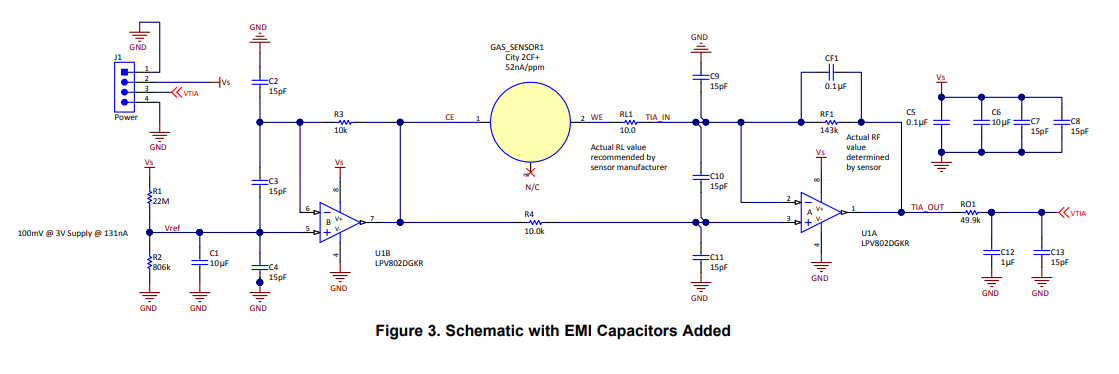
LPV802: How to simulate the phase margin of transimpedance amplifier with TINA
Since the first stage has multiple feedback loops, you'll want to open the loop at the input. I have included a simulation file below to get you started. You will need to add your model for the gas sensor. Then, you should test each amplifier one at a time. You can use this setup to test the second stage stability as well. Here is a presentation explaining the method. See slide 13 for the summary of the setup.
I would do that as shown below. The problem is that it's very difficult to find an equivalent circuit model of the gas sensor. The only one I found consisted of a resistance of several hundred Ohm in parallel with a HF capacitance and in parallel with a current source. Not sure whether this model is also valid for the sensor in the appnote.
There are two phase stability analysis to be done, one for the left LPV802 and one for the right LPV802:
The problem of self-excited oscillation is caused by instability resulting from a pole that goes too low in frequency. This pole, or poles, will encroach upon the closed loop response of the amplifier and diminish the phase margin. Instability results.
The cause of this pole is the interaction of impedances. For example, the feedback resistor might react with the input capacitance to create a pole. Or, the output impedance might react with the load capacitance.
In your case, adjusting the value of CF1 or RO1 would help, depending on where the pole is being created. Kai has suggested adjusting CF1 and I think that is probably the way to go.
However, it would help if you had a model for the gas sensor so we can be sure about the phase margin. Do you have one you can provide? How do you know the circuit is unstable? Did you simulate or build it?
If you have a gas sensor data sheet, I will build a full model in TINA and we can simulate with some more confidence. Else, I will just do my best to approximate a model, as Kai has done.
Here are some further comments from Paul Grohe, author of the article being discussed.
No…I did not model the stability fully…I just used large output resistors and feedback cap. Gas sensors respond in seconds, so “speed” was not an issue. So it is heavily damped to keep the noise down and add some averaging.
Alphasense has an appnote on modeling a sensor. Essentially they are a big nF capacitor:
Watch the capacitive paths to the output. The sensors are a big capacitor, and the feedback capacitor can create a capacitor load on the output through the series path of the feedback cap and the sensor on the input. It may be necessary to add an isolation resistor between the sensor and the input.
Here are simulation files for stability for the first and second stage of the circuit. They're set up a little different than Kais' files. I will leave it up to you to determine how best to simulate your sensor.


