This thread has been locked.
If you have a related question, please click the "Ask a related question" button in the top right corner. The newly created question will be automatically linked to this question.
Hi Team,
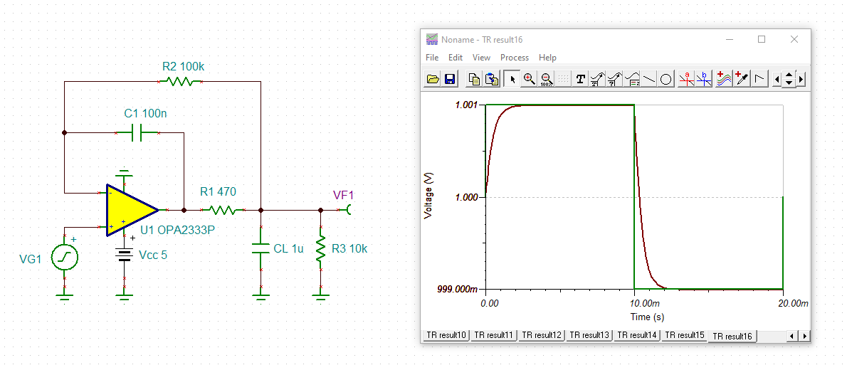
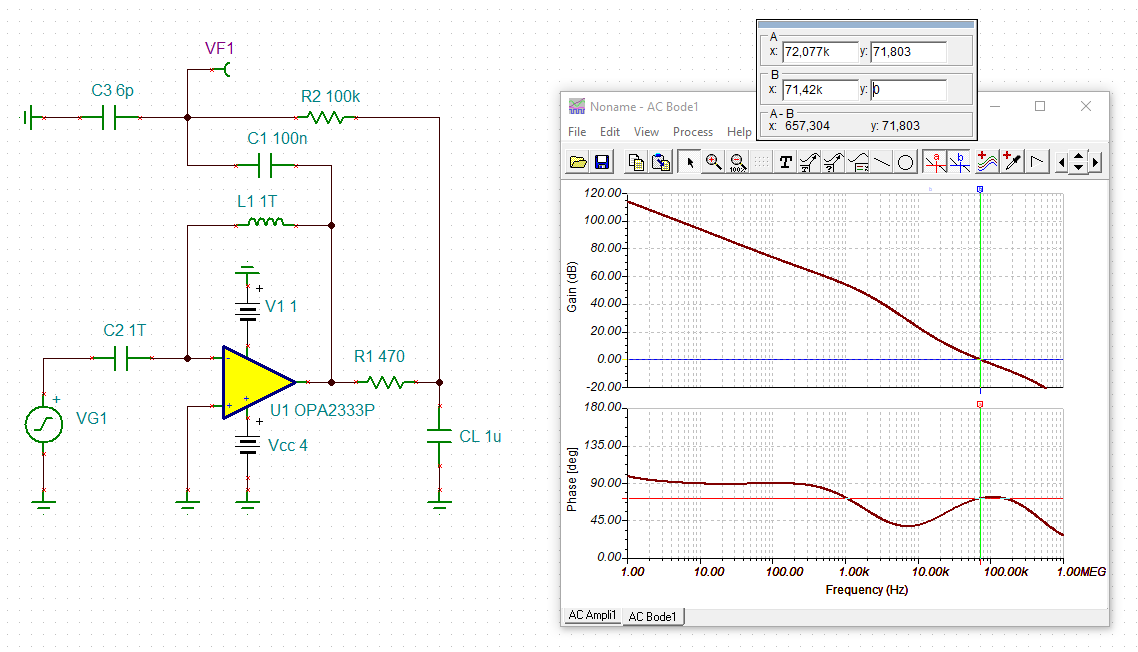
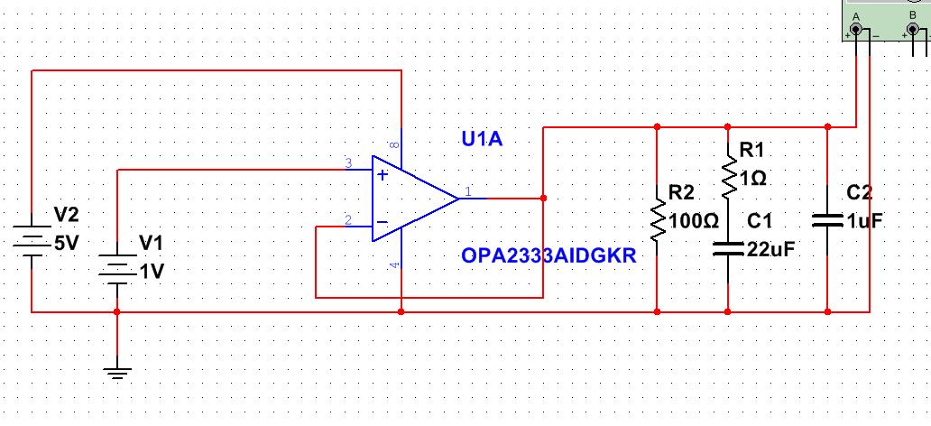
My customer designs a scheme to increase capacitive load ability, as shown below. They want to check two things with product line:
1. Is this scheme is workable or not?
2. If below scheme were workable, how to calculate the value of R1 and C1?
Best Regards,
Stanley Dai.
Well Stanley,
that 100ohm load is pretty heavy also for this part - actually, you should point them to the imbedded integrator (or dual loop) approach to driving heavy cap loads -
This comes down to a phase margin question and then what performance metrics they might have,
discussed in this thread,
Hi Stanley,
I don't think that OPA333 is able to drive 1V/100=10mA for 100 Ohm load. Yes, I am able to compensate the 1uF at the output, but you may not have much BW left in the circuit.
If you want to drive high output current, maybe we are able to place a buffer BUF634 or similar at the output of OPA333, or change to different Op Amp. Please let us know what is your design requirements.
Best,
Raymond
Hi Stanley,
provided the load current is not too high, you could do it this way:
The phase margin is 72°.
Kai