This thread has been locked.

If you have a related question, please click the "Ask a related question" button in the top right corner. The newly created question will be automatically linked to this question.

LM358B: bad behavior when signal to input comes before power supply goes up

Part Number: LM358B
Other Parts Discussed in Thread: UCC28C45, , LM358

Hi,

customer's main power stage is as below:

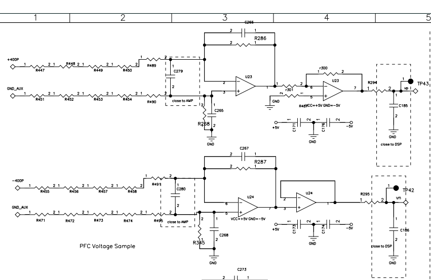
And the sampling circuit to sense +VDC(up to +400V max) and -VDC are shown below:

U24 is LM358B, the power supply is ±5V。±5V is generated through UCC28C45 from +VDC. So GND is isolated from GND_AUX.

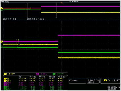
The first time we connect 3 phase AC input to grid, we measured the waveform as below:

purple- +5V supply, yellow- pin7 of U24, green- -5V supply.

The output of the OPA pin 7 should be -250*(-5.6k/850k)=1.64V which should be positive, but we get negative output with pin 7.

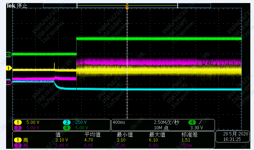
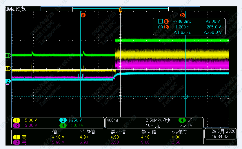
green and purple- power supply, blue- -VDC(-400P in the schematic), yellow- pin 6 of U24.

We can see that -VDC signal comes before ±5V is supplied to OPA.

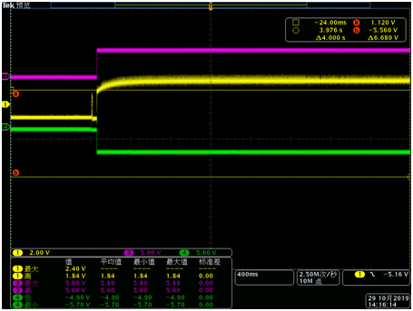
And then we disconnect AC input, wait for DC BUS decrease and aux power for ±5V for LM358B shutdown, and then we reconnect AC input. This time the output is normal as shown below:

yellow- pin7 the other 2 are ±5V.

we also measured pin 6(yellow) and -VDC(blue, it's reversed so the waveform is positive).

-VDC is measured by differential probe connecting to GND_AUX and -VDC.

This time we can see that -VDC signal comes at the same time with ±5V power supply.

So it seems that the problem is caused by -VDC comes before the power supply of OPA. But according to the waveform, pin 6 is 0V before ±5V is supplied to LM358B, which doesn't go beyond the recommended operating conditions.

Why would LM358B behaves abnormal in such situation?

The customer is always using AS358 and it doesn't have such problem.

  • Howard,

    I suspect the voltage difference between the different ground systems may be changing the common mode voltage. Can you measure the voltage pins 5, 6, and 7 when the op amp is in the unwanted output state?

  • pin 5 and pin 6 is around -0.5V, pin 7 is -5V. Looks like the OPA is saturated somehow.

  • Hi Howard,

    I would add silicon diodes to clamp the input voltages to a potential > -5.3V.

    Kai

  • Howard,

    If both inputs are the same then the op amp did it's job. Did you keep a meter on pin 7 when you checked pins 5 and 6? Or at least re checked that pin 7 was still -5V?

    Another odd thing, I don't think output could be -5V with input at -0.5V and feedback resistor is 5.6k ; that would require (-0.5V - -5V)/5.6k = 804uA of sink current and the LM358B VOL is about GND[pin] + 0.7V at that current. -4.3V would have been possible, but -5V is not possible (barring a short or pin 4 not being -5V). 

  • Hi Howard,

    the LM358 is in risk to be damaged, if GND and GND_AUX can freely flow against each other. The LM358 should be protected somehow. If this is too much trouble, I would switch to an isolation amplifier.

    A protection circuit could look like shown below. First the performance with regular signal:

    Then the performance with common mode voltage between the two grounds (GND and GND_AUX):

    How does it work?

    The diodes clamp the input voltages to the supply rails, while the resistors between the clamps and the inputs of OPAmp provide an additional voltage division. This keeps the input voltages within the allowed input voltage range and prevents the violation of absolute maximum ratings:

    (The OPAmps were removed because the Spice model doesn't work properly with zero supply voltage.)

    howard_lm358.TSC

    The disadvantage of such an enhanced protection scheme is that all the resistors (except for R8) have to be very well matched to keep the common mode rejection high. Because of this I would take +/-0.1% precision resistors.

    Kai

  • Kai,

    thank you.

    Personally I guess the problem is latch issue, I'll test on our own board by giving signal to input prior to the voltage supply.

    The problem you listed about the common mode voltage should also be a problem for AS358, but it doesn't.

  • Howard,

    There will be different response for input voltage below the GND pin for each design for 358. On one design, the output may go high. On other design device, the output may go low. For most (may be all) the 358 will resume normal (closed loop) operation once the input voltages return to valid input voltages. The same thing can happen for input voltage above VCC-2V.