This thread has been locked.

If you have a related question, please click the "Ask a related question" button in the top right corner. The newly created question will be automatically linked to this question.

LMC6001: Noise appeared on pA-nA a transimpedance amplifier

Part Number: LMC6001
Other Parts Discussed in Thread: LM7705

I tried to make a transinpedance amplifier for measuring pA-level current from a photodiode.
I confirmed that DC-light signal was shown using an oscilloscope.
However, 50Hz signal appeared and overlapped with the DC-signal.


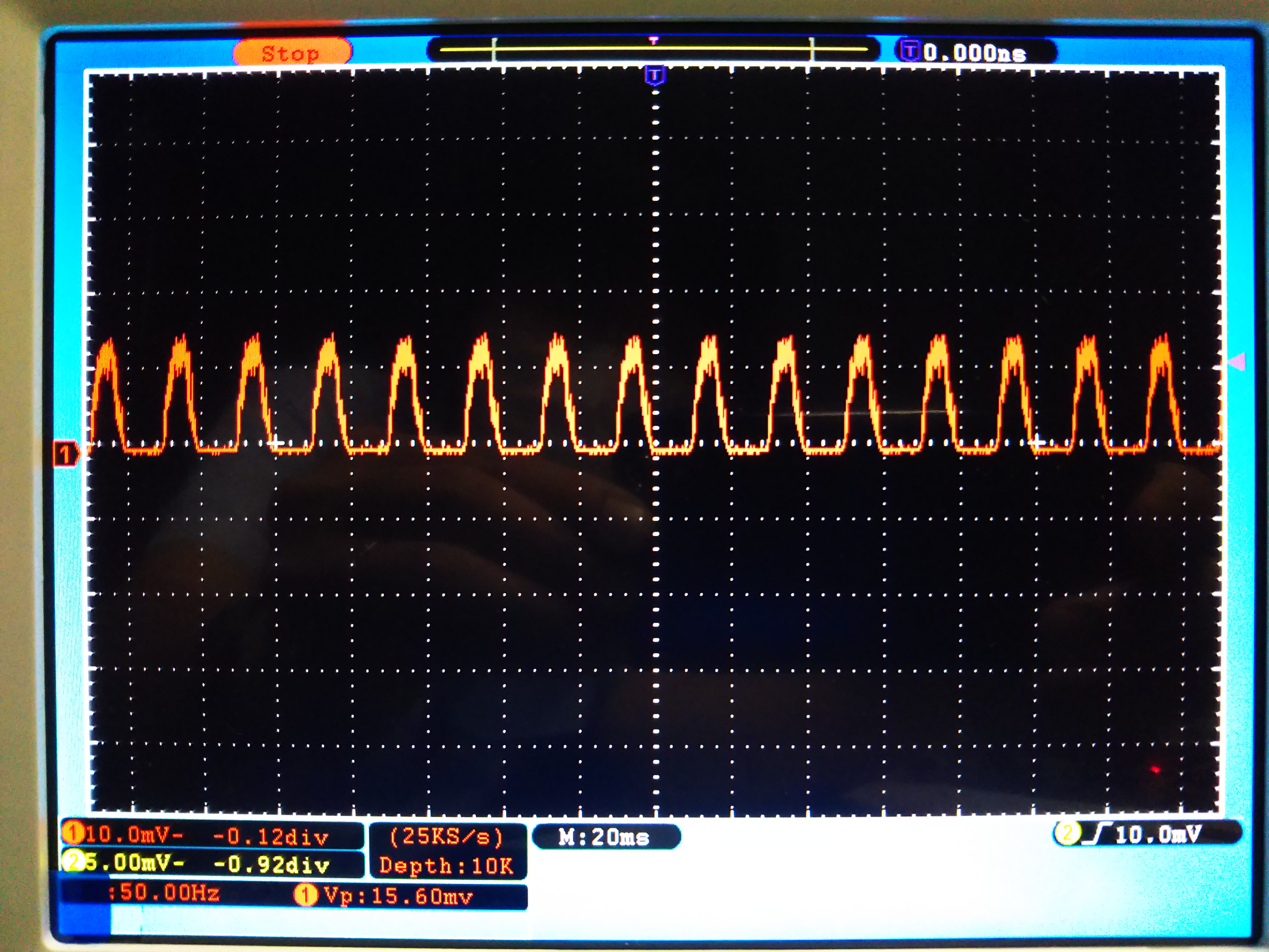
When I turn off the 9V battery, the 50Hz noise signal noticeably increased.


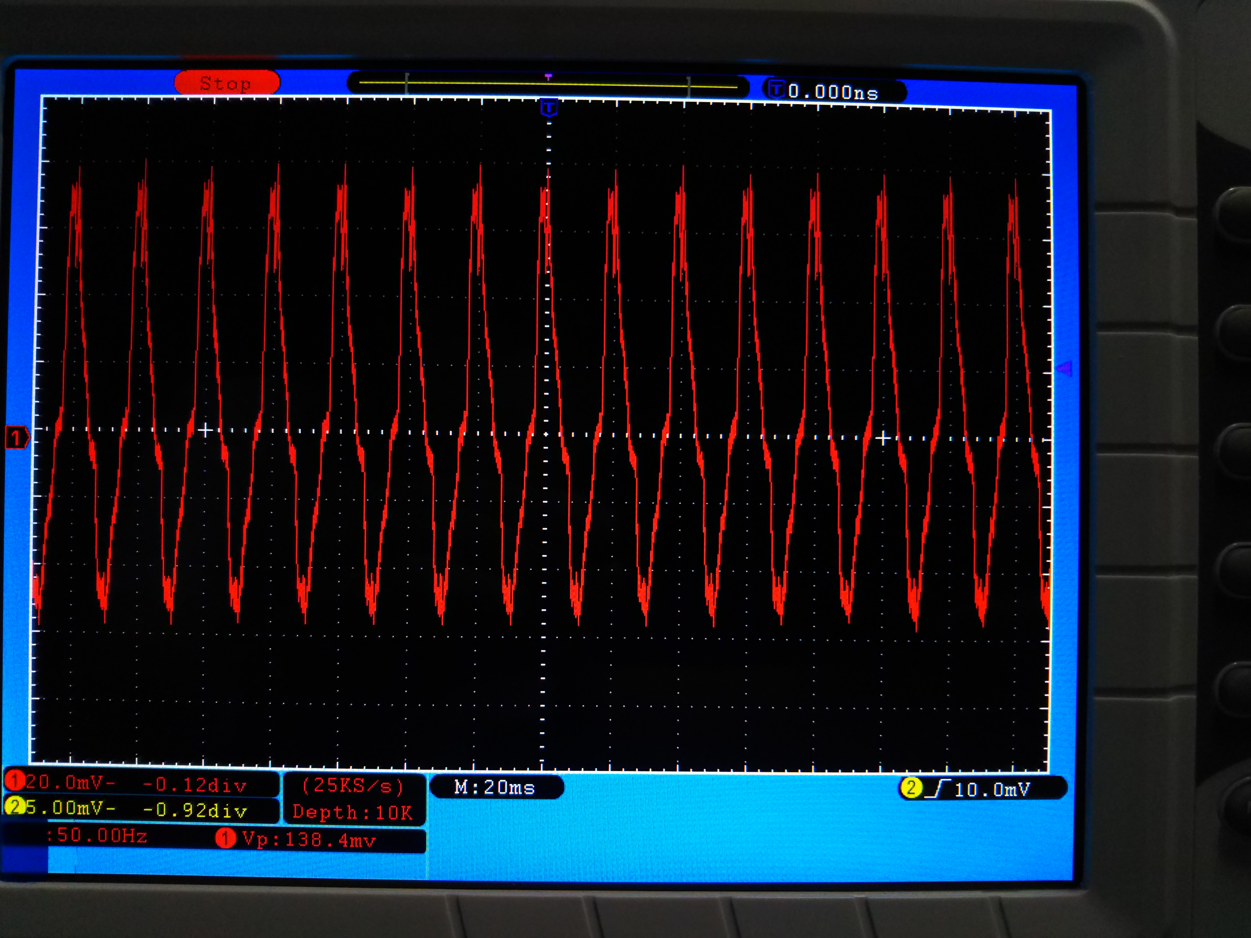
I have two questions.
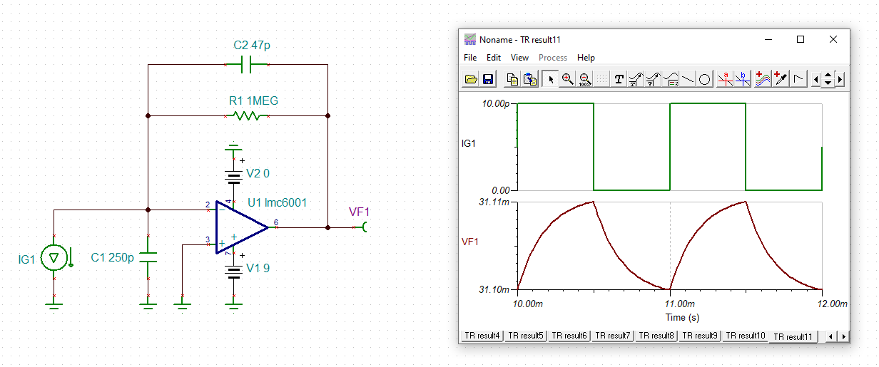
1. Is the attached circuit wrong?
2. Why the circuit detected 50 Hz signal?

I need your support. Thanks in advance.

  • Change the feedback to 8pF, should give a Butterworth at about 28kHz BW

    This is a really old part with very poor input voltage noise, newer parts might do better noise wise, 

  • Hello k s,

    Michael has provided good, useful advice for improving your transimpedance circuit performance. Please consider his recommendations.

    Additionally, your LMC6001 transimpedance amplifier (TIA) circuit has a transimpedance gain of 1 million, which is very high. Fifty or 60 Hz line frequency fields in your test circuit location can end up being picked up by the circuit board/ wiring and end up being amplified by the TIA circuit.

    It is best to enclose your TIA circuit in a metal enclosure and power it from the 9 V battery mounted inside the enclosure. We often use a small aluminum box, or even an unused paint can as the enclosure for test purposes. An opening in the enclosure can be provided for the photodiode so that it can receive the light from the light source, but keep the opening to a minimum. The output of the TIA should be routed to a coaxial connector mounted to the metal enclosure. A coaxial cable can then be used to bring the TIA output signal from the output connector to any circuit that follows.

    Regards, Thomas

    Precision Amplifiers Applications Engineering

  • Hi k s,

    the output of LMC6001 saturates:

    ks_lmc6001.TSC

    Add a negative supply voltage or add bias voltage to prevent the output of LMC6001 from saturating:

    Also, as aleady mentioned by Thomas, shield the circuit with a metal enclosure and connect it to signal ground.

    Kai

    PS: Sorry Thomas, I didn't see your post :-)

  • Hi ,Michael,

    Thank you for your support.
    I change the capacitance to 10pF (I did't have 8pF).

    I have one question.
    In this case, the circuit works safety with feedback capacitance lager than 8pF, right?
    If I use 100pF, it will only decrease the BW, right?

    Sincerely,

    K.S

  • Dear Thomas,

    Thank you for your support.
    Your good explanation is very easy to understand, and I convinced.
    I will try to enclose in a metal box within a few days.

    And, I would like to convert sub-pA-order current from a photodiode to sub-μV-order voltage.
    If you have an idea, would you teach me?

    Sincerely,
    K.S

  • Dear Kai,

    Thank you for your support.
    Your advice is helpful.
    I confirmed that the simulation result using your model.

    I would like to use the circuit by using a battery.
    In this case, how can I get negative voltage?

    Sincerely,
    K.S

  • KS, use the LM7705

  • Hello k s,

    There is a lot of published information on line regarding the design of transimpedance amplifiers. One example is the in the Analog Engineer's Circuit Cookbook: Op amps, published by TI. See Page 34, "Transimpedance Amplifier Circuit" for the step-by-step design procedures:

    https://www.mouser.com/pdfDocs/analogengineer%E2%80%99scircuitcookbookopamps.pdf

    The information is also available as in video format from TI training:

    https://training.ti.com/how-design-transimpedance-amplifier-circuits

    Successfully implementing a high performance, sub-picoamp input transimpedance amplifier is going to be a challenge, but I think the information that Michael, Kai and I have provided should get you moving in the right direction.

    Regards, Thomas

    Precision Amplifiers Applications Engineering