This thread has been locked.

If you have a related question, please click the "Ask a related question" button in the top right corner. The newly created question will be automatically linked to this question.

AMC1200: Input resistor

Part Number: AMC1200

Hi team,

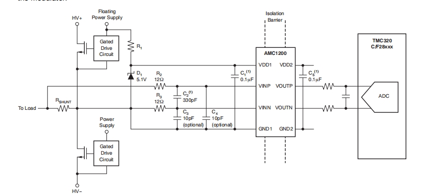
After the input filter resistors R2 and R3 of our AMC1200 are changed, the algorithm in Figure 2 will be affected. What specific requirements are there for the resistance value of R2, R3 and C2, or how is the relationship of these vaules

    If R2 R3 is 10K and C2 is 100nF, how to calculate the multiple relationship?

        In Figure 2, R1 is 150K, R2 is 12.2K, RIN28k, and the multiple is 0.053. 
The resistance of R2 and R3 is added to the RIN resistor or ignored. The obtained multiple cannot be consistent with the original algorithm
  • Hi Jeff,

    R2, R3, and C2 make up the anti-aliasing filter for the input of the device. 

    Their cutoff frequency is 1/(2*R2*R3*pi*C2)

    Typically, we recommend that the cutoff frequency be around 1MHz. 10ohm for R2 and R3 with 8.3nF for C2. 

    Common-mode capacitors, C3 and C4, can also be used for additional filtering, and typically are 10x or smaller compared to C2. 

    I certainly would not recommend using 10kohm for R2 and R3, as a significant voltage drop would occur across these resistors before reaching the input pins of the device. 

    Please let me know if you have additional questions.