This thread has been locked.

If you have a related question, please click the "Ask a related question" button in the top right corner. The newly created question will be automatically linked to this question.

LMH5401: LMH5401 drive ADC

Part Number: LMH5401
Other Parts Discussed in Thread: OPA858

Hi,

I am trying to use LMH5401 to convert single ended input to differential , amplify and then feed to ADC Input channels.

The power for LMH5401 is 3.3V,the CM voltage is 1.65V. The input signal is pulse voltage,50MHz.

Below questions:

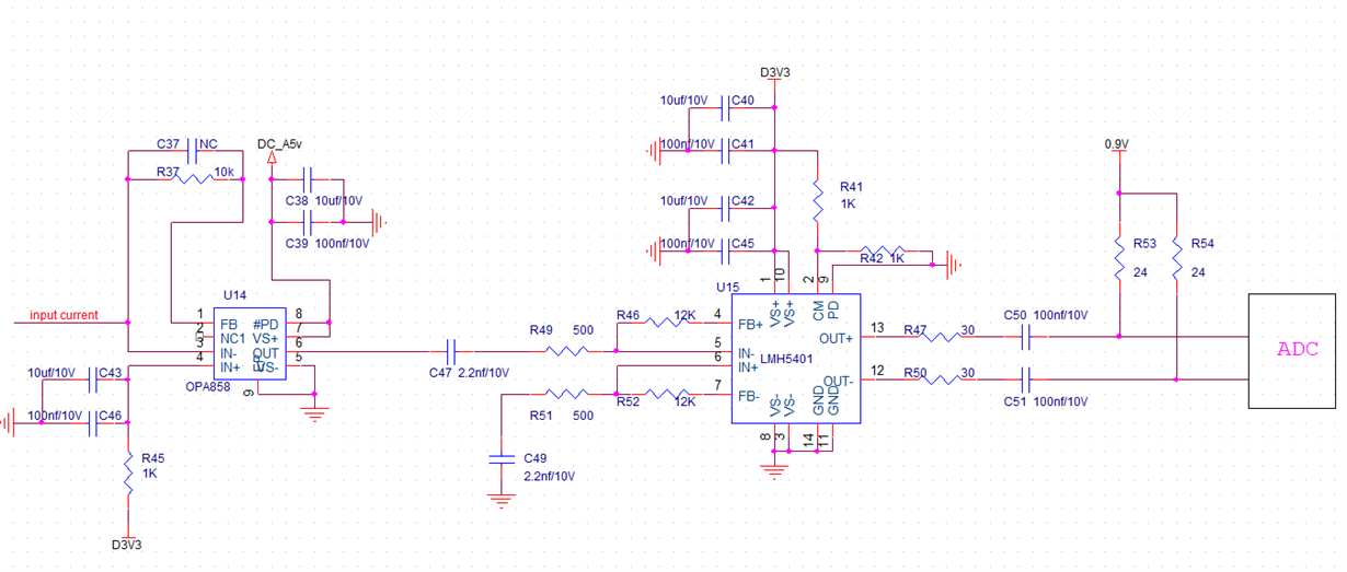
1. When the differntial output of LMH5401 is floated,i  test the waveform with a oscilloscope.I must set the impedance of the probe as 1M ohm,then i can see the 1V saturated swing.If i set the impedance of the probe as 50 ohm,both the CM voltage and swing will become lower.

2.I config the circuit of LMH5401 as a  24X amplification,RG and RF are 500 ohm and 12K ohm.

The output of LMH5401 connect to an ADC chip.the bias vlotage of ADC is 0.9V, so i need to change the 1.65V CM voltage to 0.9V.

Refer to the figure:

When i test the above circuit,i find that the saturated swing of LMH5401 output become lower.

I removed the ADC chip,no improvement.

If i remove R53 and R54,the saturated swing will be 1V.

What i needed is change the bias voltage to 0.9V,and don't reduce the saturated swing.

Waiting for your reply.

Thanks.

  • Hello Wenhui,

    1. When using a 50-ohm differential output the CM voltage and swing are lowered due to the voltage division that is occurring between the 40-ohm output impedance (10 ohm from part and additional 30-ohm added) to the load. Typically, 50-ohm loads are used along with a 50-ohm output impedance. Although this will half your output voltage, it will help resolve reflection issues you might see when working in the high frequencies that the LMH5401 can achieve. 

    2. Similar issue here, a voltage division is occuring between R47 & R53 which is reducing your output voltage.

    I would suggest removing C50 & C51, and using the LMH5401 in a dual supply configuration with the CM pin tied to 0.9V. 

    Best,

    Hasan Babiker

  • Hello Wenhui, some comments, left to right

    1.Your OPA858 input stage appears to be a transimpedance stage, you will need to value for C37 to stay stable (will need your source C to compute that) 

    2. Your I/O for the LMH5401 are all AC coupled, that means the DC levels can be set inside there seperately to be ideal for the LMH5401,

    3. Your 12kohm feedback is a bit high for the LMH5401, The OPA858 is specified with 200ohm load, why not go to that with a 4.75kkohm feedback, increase the input C's to 5.6nF and add a 100pF parallel value for self resonance issues

    4. That  24.75 NG in the LMH5401 means it will have 300Mhz closed loop BW (about), plenty for your 50MHz pulse I think

    5. You cannot bias the CM pin to the supply, this FDA does not default on the CM to mid supply, drive the CM pin with your 1.65V bias voltage with decoupling cap. 

    6. Usually not necessary to doubly terminate from the FDA output to the ADC, taking uinnecessary insertion loss - do need to consider the ADC input impedance and CM bias current (sometimes) I would start with that ADC input Z and maybe design for only a 0.9X insertion loss solving for the required series output R's and blocking C. 

    7. Yes, just bring in the 0.9V bias for the ADC through two larger valued R's (on the output side of the blocking caps) and account for its common mode bias current (pipeline ADC's will have a clock rate dependent common mode current that has to be accounted for. 

  • Hello Michael,

    Thanks for your kindly reply!

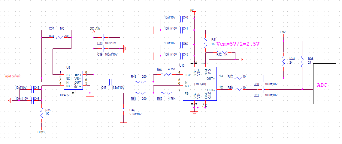
    I changed the circuit refer to your suggestion.

    Below is the new circuit:

    1.According to my test results,when i removed C37,the output of OPA858 was stable.Is the C37 necessary?

    2.I changed the feesback resistor for LMH5401 to 4.75K,and incerased the input C's to 5.6nF.If there is no self resonance issue,is 100pF necessary?

    3. The CM pin voltage is VCC/2,i set two 1K ohm divide from VCC.

    4.I need the ADC input SWing up to ±500mV when the output of LMH5401 saturated. I think the VCC voltage 3.3V i used is too small,so i change the VCC voltage to 5V this time. 

    5.At the ADC input side ,if i set the larger value of R's,the falling edge of the waveform will become slow.So i use the 24ohm to ensure the BW.

    I have not debug the above circuit.

    Do you think there is still a problem with this circuit?

    Thanks very much.

  • Hello Hasan,

    Thanks for your kindly reply.

    If i set the LMH5401 in a dual supply configuration with the CM pin tied to 0.9V,The supply voltages are not common.

    I plan to change the supply voltage to 5V,the CM voltage is 2.5V,to increase the output swing.

    Do you think it will be work?

    Thanks very much.

  • Well Wenhui, 

    1. you need to add the current source capacitance to see the instability

    2. You need to add the self resonance L of the blocking caps  to see that issue

    3 Yes, mid supply is good for the Vcm, you need to add a cap there for noise reduction

    4. You don't want to saturate the LMH5401 outputs as that causes recovery time issues

    5. Can'r really do the LMH5401 to ADC design without the ADC input impedance described. part number would help.