This thread has been locked.

If you have a related question, please click the "Ask a related question" button in the top right corner. The newly created question will be automatically linked to this question.

LM211: response time difference between datasheet and real test

Part Number: LM211
Other Parts Discussed in Thread: LM193, AM26C31

response time in LM211 datasheet:
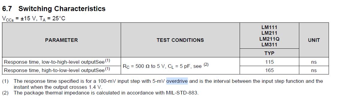
maximum is 165ns.

But it's different with TINA result and real test. (same circuit)
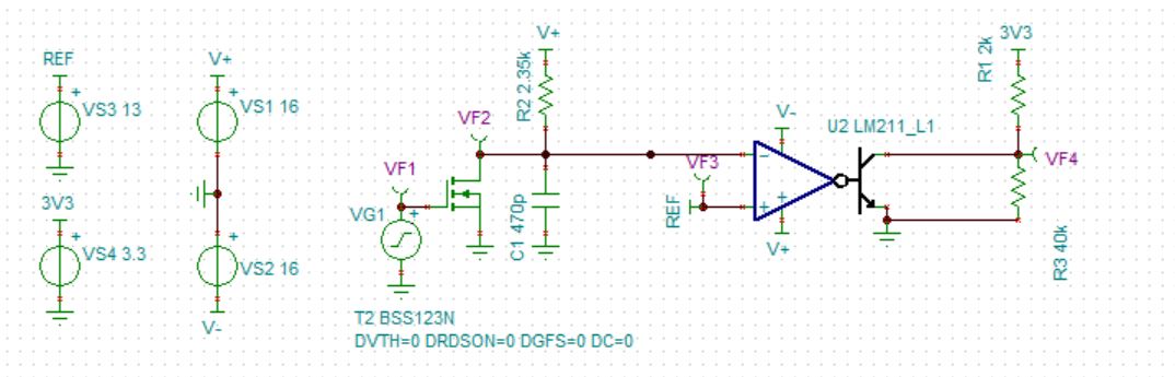
1 TINA result: around 30ns with C1=470p or C1=NC. Green is VF3, yellow is VF2, cursor a is VF2=VF3. red is VF4.

2 REAL TEST

result: C1=470pF, response time is 600ns,C1=NC, response time is 2.28us.

same circuit with TINA.

C1=470PF

C1=NC

Customer want to get quick 165ns as datasheet described. what's your suggestion? thank you!

Yuan

  • Hi Yuan,

    see the test condition:

    For fast switching a low pull-up must be used. Also, the input signal must provide fast rise and fall times.

    Kai

  • Hi Kai,

       Thank you for your replying.

    The real test result show that  the faster the rise time, the greater the delay. Can you help me analyze it.

    I will reduce the pull-up resistance and show you the result.

  • add  test results:

       pull-up resistance R1 is reduced from 2k to 0.33k,high-to-low-level output response time is not changed.

    Lowering the reference voltage(IN+=13V reduce to 4V) reduces the high-to-low-level output response time,from 2.28us to 0.64us.

  • One thing that I am wondering is if violating the min input voltage range is causing some delay to the response time of the comparator.

    If you note in the EC table, the LM211 does not allow the input range to go all the way to ground.  the lower boundary is 0.5V above (VCC-).  In the case where C1 is not present, the input rise waveform is very fast and thus the time from being outside the common mode range of the device to when the waveform crosses the threshold is short.

    Also note that when the input goes from high to low, the response time is very fast potentially because the input range is not being violated.

    I suggest you level shift the input up so the min voltage is 0.5V above (VCC-) and see if that has a impact on the response time.

    Chuck

  • Hi Chuck,

         Please check the schematic and test waveform of the initial problem. The power supply is  ±16V, the input reference voltage is 13V, and the input RC circuit is charged from 0V。

  • Hi,

    you should not allow the input voltage to fully rise up to the positive supply voltage of LM211 because you will leave the common mode input voltage range at the end of rising. This is not a problem with C1 installed or Vref=4V because then the output of LM211 has enough tome to toggle low before the input voltage leaves the common mode input voltage range.

    So connect R2 to a voltage which does not exceed "positive supply voltage" - 2V = 16V - 2V = 14V.

    Kai

  • While Kai's point is valid that you are violating the input range, this does not appear to be the problem because when the input goes from high to low, the output response time is good (quite fast).  I am starting to think that the difference in response time is more related to the underdrive level.  In the instance when the cap is not present, the input moves quickly from 0 to 16V, so the underdrive seen by the comparator is 13V (this is quite large).  When the cap is present, the input slowly creeps up on the 13V threshold, so the underdrive is quite minimal and this could explain the faster response time.  Another piece of data that supports this is when you experimented with moving the switching threshold down to 4V.  Now the underdrive is only 4V, which could explain the better response time but this could also be impacted by the overdrive being much larger as well.  But I am betting the underdrive level which is often overlooked is the root cause of the difference. If you have the ability to change the input to swing from 9V to just beyond 13V, it would be interesting to see if the response time improves.  The key point is that underdrive and overdrive both impact response time.  And sorry for missing that the low supply level was -16V, I had previously focused on the waveforms and missed that.

    Chuck

  • Hi Kai,Chuck,

        Tks。I have two more questions。

    Q1:Why can't the TINA simulation get the measured response time,I downloaded the PSpice model from the TI website

    Q2:I want to convert the differential signal(AM26C31) to a single-ended signal(VOH=15V,VOL=0V),I should use the RS422 receiver or the comparator such as LM211 or LM193.

  • The model for the LM211 is quite simple and unfortunately does not model the variation in output response time variation to input UD and OD.

    The LM193 does not have the same output structure as the LM211.  Based on your usage case of requiring a split power supply, the LM211 is the only comparator in our portfolio that will allow the output swing down to 0V.

    I am not familiar with the RS422 receiver, so I would not be able to provide comment on that.

    Chuck

  • Hi Yuan,

    you might want to read this:

    slla070d.pdf

    Kai

  • Hi,

    you might want to read this:

    4188.slla070d.pdf

    Kai

  • Thank you Kai for providing the suggestion.  I will leave this post up in case there are additional questions regarding our comparators.

    Chuck

  • There has not been any new post on this thread, so it will be closed.  If further support is required, please reply or feel free to open a new thread.

    Thanks

    Chuck