This thread has been locked.

If you have a related question, please click the "Ask a related question" button in the top right corner. The newly created question will be automatically linked to this question.

Question in Amplifier Presicion Lab : Stability

HI Team,


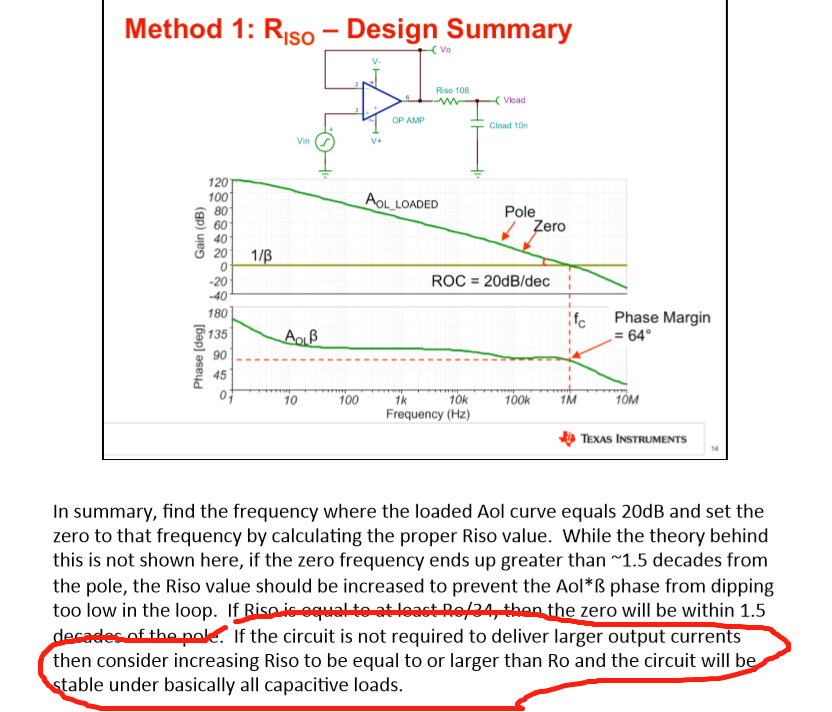
1. Question 1 :According to the video in Stability 5, I want to know why the circuit will be stable no matter what value of the cload when the Riso is larger than the Ro?

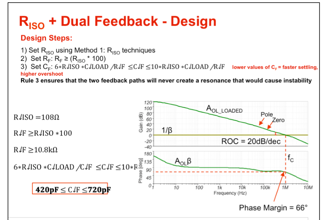
2. Question 2 :According to the video in Stability 6, I want to know why the value of the CF should be selected in that range according to the rule 3 and how does this range of CF came out?

Best regards

Zhihong Huangs

  • Hi Wesley,

    Question 1 :According to the video in Stability 5, I want to know why the circuit will be stable no matter what value of the cload when the Riso is larger than the Ro?

    The objective of Op Amp compensation is to maintain a single pole roll off at -20dB/decade in a loop gain. When an op amp's output circuit introduced Cload, a pole is generated in the closed loop. In order to maintain -20dB/decade, you need to cancel the pole with a zero.

    When Riso is introduced at the output of op amp circuit, it creates a voltage divider, and the transfer function is shown in the image below. The zero from Riso*Cload is canceling the pole generated from (Ro + Riso)*Cload. If Riso is larger, then the fp will be smaller or lower. Since the phase of fzero is started a decade earlier, it will be more effective to compensate the phase angle with large Riso, if large Riso is possible. 

    Enclosed is the link of Op Amp Stability Series, and it is well explain in the video. 


    https://training.ti.com/ti-precision-labs-op-amps-stability-capacitive-loads?context=1139747-1139745-14685-1138805-13952

    I am going to answer your Q2 in a seperate reply. 

    Best,

    Raymond

  • Hi Wesley,

    Question 2 :According to the video in Stability 6, I want to know why the value of the CF should be selected in that range according to the rule 3 and how does this range of CF came out?


    There is an error in one of Cf expression. The following equation is the correct one. 


    The Riso + Dual Feedback circuit is shown in the above image. When Cf behaves in short, its value is approx. at 1/10th of fzero or fzero = 1/(2pi*Riso*Cload). When Cf value is at the suggest max. value, the op amp step response tends to be underdamping. The lower suggested value in Cf is approx 1/6th of fzero frequency. Lower value in Cf will result faster response and overshoot (tends to be less stable). Ideally, you want to pick a value between the two extremes. 

    This equation is suggested as rule-of-thumb (it has something to do with Q of the compensation circuit). Often,  it is easier to enter a Cf value in range, and inject small and/or large signals in step function, and adjust the Cf value according to op amp's damping responses.  

    Best,

    Raymond