This thread has been locked.

If you have a related question, please click the "Ask a related question" button in the top right corner. The newly created question will be automatically linked to this question.

THS4551: Amplifier output operation

Part Number: THS4551
Other Parts Discussed in Thread: ADC3221,

Hi Ti.

I'm confusing, why output voltage isn't match my calculation.

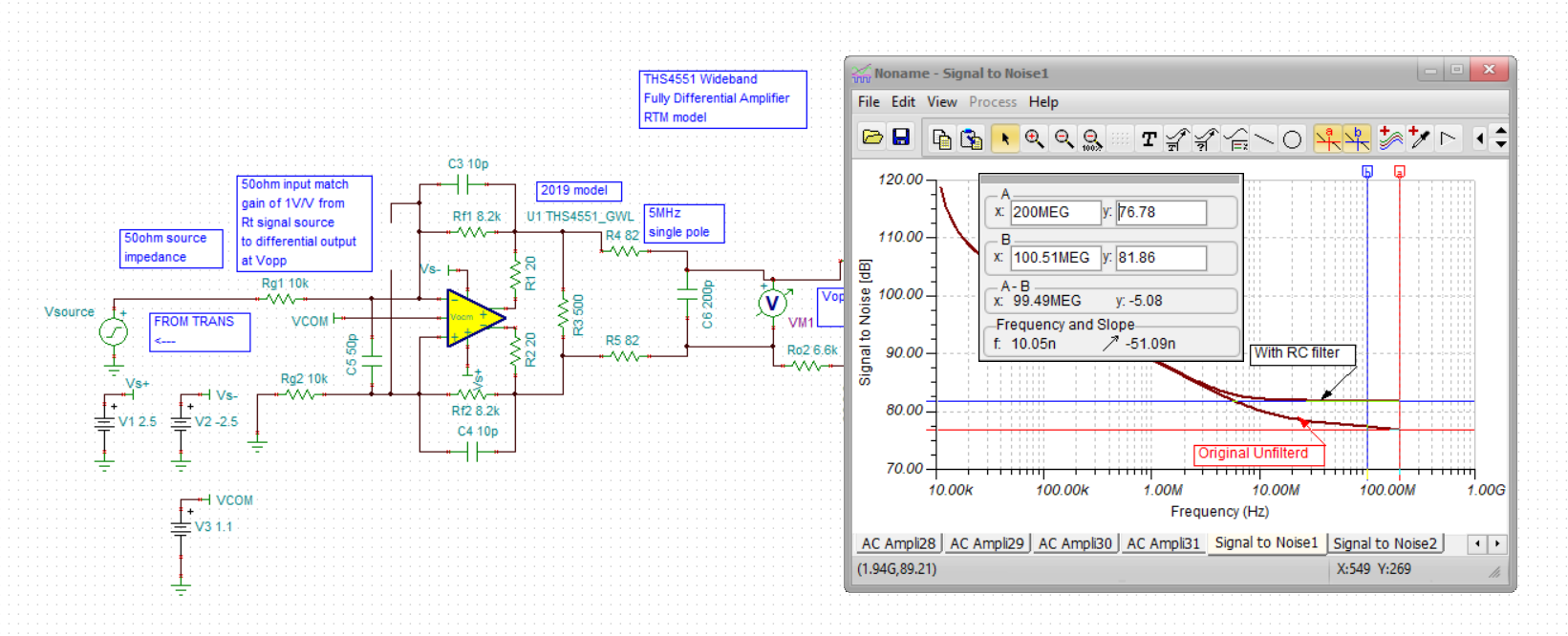
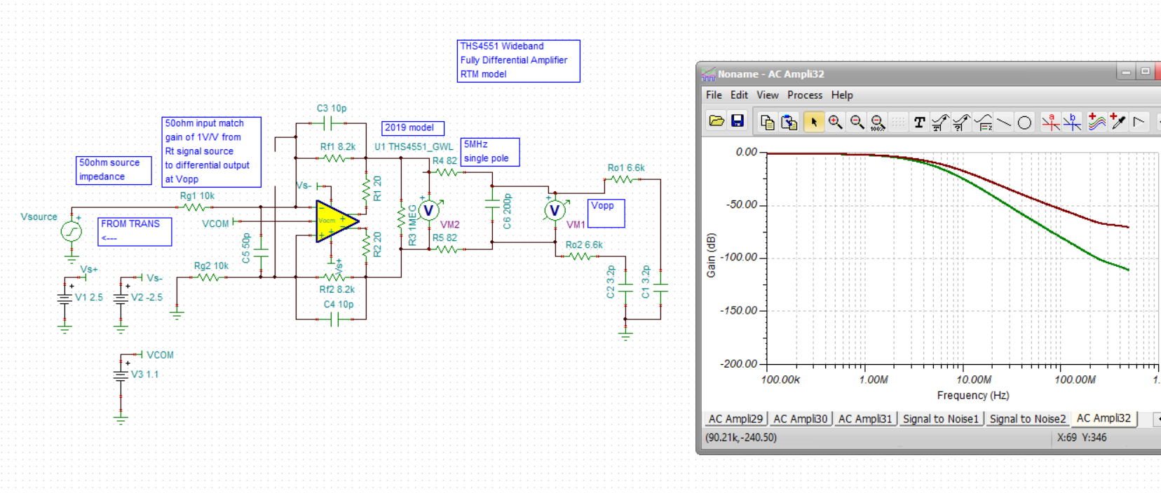
Please show my schematic.

This schematic is single-end input to differential output for ADC3221.

So VOCM voltage is from 0.8 to 1.1V.

I desinged attenuator 0.8V/V. But output voltage is almost VOCM ± 0.4V when voltage source set 1V amplitude Sine Wave.

FDA_THS4551.TSC

Could you analyze why this happen?

Sincerly.

Yuzuru.

  • Your source is actually +/-1V in the sim file - 

    1. you are not stable right now, 

    Your differential output swing is correct for a +/-1V input

    Here I fixed the instability with a few changes - I think the THS4551 needs some load, 500ohm diff here. 

    Also your output RC is using too high R and to low C. 

  • Hi Michael.

    Thank you for your comment.

    I'll give you more detail.

    Output RC is the impedance of ADC3221 INA or INB.

    Input voltage frequency is 1MHz.

    Is this cirucuit stable in my frequency range ?

    I understand this circuit outputs a differential voltage that is 0.8V/V times the single-ended input voltage.

    So the voltage of 0.8/2=0.4V/V is output for each output voltage terminal ( differential ).

    Why THS4551 needs some loads?

    OPAMP doesn't necessarily require a load.

    Sincerly.

    Yuzuru.

  • 1. Not much in the ADC3221 datasheet for analog input circuit - but most of these pipeline ADC's want to see a cap looking out, once you add that you need a small series R to isolate it - and in any case you can add more filter there using an RC or RLC to help control Nyquist (apparently signal BW is 1MHz)

    2. As is the circuit unstable - you don't care if its in your frequency range (not, more like 140Mhz) because if it is oscillating you will fail EMC

    3. You are putting in 2Vpp which will generate and output differential of 1.6Vpp, divide by 4 and each output is swinging +/-0.4V around the CM set point

    4. The THS4551 is more aggressively compensated to give high BW on low power - that means the phase margin starts out lower. It also has a very reactive open loop output impedance so the loading gets into the loop gain a lot more. I added those inside the loop output R's which normally helps for those feedback C effects - they didn't until I added the differential 500ohm. 

  • Need for interstage RC filter

    I looked a little for this, this document has a lot in it but look on page 13 figure 13 - essentially you need something there or your SNR will be unnecessarily degraded.I usually use an RLC filter to get more integrated noise reduction. 

    https://www.ti.com/lit/an/slaa416a/slaa416a.pdf?ts=1593701287090&ref_url=https%253A%252F%252Fwww.google.com%252F

  • I went ahead and working on some SNR comparisons - several issues, 

    1. The file you sent in was the original 2016 model I worked on - for some reason it would not run a noise sim so I had to update to a July 2019 model I had

    2. Some earlier testing showed that model is at 2.5nV input voltage noise vs actual 3.3nV, they may have fixed  but just needed to show delta with and without postfilter

    Here is your ckt SNR at ADC input assuming 1.8Vpp max signal, 

    Here is same with a 5MHz RC filter from FDA to ADC, yes we get a 5dB SNR improvement

    With that RC in there, probably do not need the 500ohm diff load, yep, you can get rid of that. 

  • And the TINA file with the 2019 model and RC filter

    FDA_THS4551 2019 model with postfilter.TSC

  • Hi Michael.

    I can't open the file you attached. Could you send me agein?

    I've read slaa416a and I understand what you said.

    Some LPF is needed for high-speed ADCs input to improve SNR.

    And LPF schematic that you designed is differential filter.

    One more question.

    You added R1 and R2 in your schematic, what role are they?

  • Well I had saved it as a v7, here is a V9 version - I try those R1 and R2 if the stage is not stable, once the filter is in there (a heavy load at higher F) you don't need them. 

    8546.FDA_THS4551 2019 model with postfilter.TSC