This thread has been locked.

If you have a related question, please click the "Ask a related question" button in the top right corner. The newly created question will be automatically linked to this question.

TLV9352: Why output is different when using TLV9352 and OPA2171

Part Number: TLV9352
Other Parts Discussed in Thread: OPA2171, , OPA171, OPA172

Hi team,

My customer used OPA2171 and the SCH put in below Pic1. The cap C403, C203, C218, C209 have been removed in the board.

J13 interface is the "input" and U_OUT_ADC0 is the "output" .

The input is Differential signal and it is Square wave.(VPP=0V-70V  and frequency=100Khz)

Pic2 is the output waveform.

Customer think OPA2171 SR is not enough from the waveform.

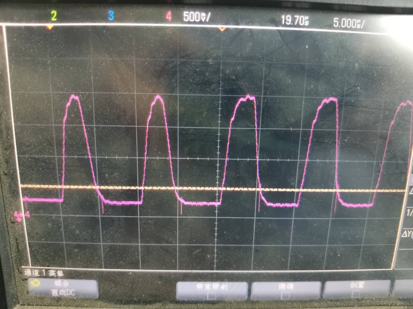
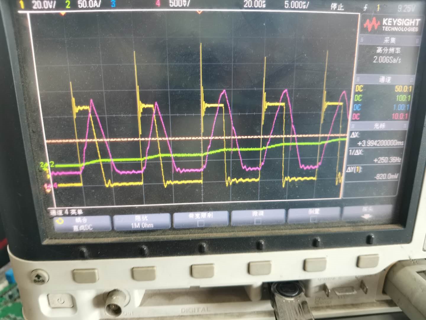
So we replace OPA2171 with TLV9352. The output waveform in Pic3, (pink one is output, yellow one is input).
It looks like TLV9352 output is worse than OPA2171.

Do you know why they are different? And what happen?

Thanks!

Pic1:

Pic2:

Pic3:

  • Hi Eggsy,

    I do not believe the input voltage is large enough to slew the output of the amplifier. So I don't think using a device with a higher slew rate will improve the performance. For the op amp to slew the inputs must be pulled apart but since there is a large resistor divider at the input the inputs will not get pulled apart enough for the op amp to slew. If the device does slew, it will be for a very short amount of time. Please see our TI Precision Labs on Slew Rate for more information.

    One recommendation, is to replace the 10kohm resistors, R421 and R422, with shorts. Placing resistors in the feedback degrades the phase margin of the device because the resistance interacts with the input capacitance of the device and creates delay in the feedback (instability). Resistors R421 and R422 are a common technique to reduce the errors associated with input bias current in bipolar devices but since this is a CMOS device these resistors are not needed.

    After shorting R421 and R422 can you please take the measurements again? Please provide scope shots of the input (0-70V), output of first amplifier, output of second amplifier, and the input of the first amplifier (please measure at R135).

    Thank you,

    Tim Claycomb

  • Hi Eggsy,

    I just realized that the input signal does not have a 50% duty cycle, like I was using in simulation. The device might not have enough bandwidth to respond to the input signal. Even with the OPA171 the waveform is barely getting to the peak voltage before going back down to 0V. Another test would be to try a device like the OPA172 which is a 10MHz device.

    Thank you,

    Tim Claycomb

  • Hi Eggsy,

    what happens when you remove D11?

    Kai

  • Hi Tim,

    Thanks for your support!

    Why input signal does not have a 50% duty cycle, it need high bandwidth device?

    Thanks!

    The first stage gain is about 15 and frequency is 100Khz, I think GBW is 3Mhz is enough? RIght?

  • Hi Kai,

    Why do you have this idea?

    Thanks!

  • Hi Eggsy,

    some zener diodes can have lots of junction capacitance and a high load capacitance would slow down the OPAmp :-)

    Kai

  • Hi Eggsy again,

    a closed-loop gain of factor 15 at 100kHz would need a minimum open-loop gain of factor 150 at 100kHz, in order to have a linearizing gain reserve (loop gain) of at least factor 10. This would mean a GBW of 150 x 100kHz ~ 15MHz (usual 20dB/decade fall of open-loop curve assumed).

    Kai

  • Hi Eggsy,

    I only mentioned the 50% duty cycle because in my simulation I was using a 50% duty cycle and not seeing an issue. With less than 50% duty cycle there is less time for the output to reach its final value.

    Even though the square wave frequency is 100kHz a higher bandwidth device might be required because the rise time of the edge for small signals is dependent on the bandwidth. The rise time is equal to 0.35/BW for small signals. Since the amplifier is only seeing a few hundred millivolts at the input which is considered small signal a higher bandwidth device will create a faster rise time. Can the customer please try the OPA172 for troubleshooting purposes?

    Thank you,

    Tim Claycomb