This thread has been locked.

If you have a related question, please click the "Ask a related question" button in the top right corner. The newly created question will be automatically linked to this question.

LMP2231: Electrical overstress of CMOS input op amp during power-down

Part Number: LMP2231

Here's how I described this situation in a case that I opened a few days ago.  The engineer who responded could not answer this question.


Short description: How to avoid electrical overstress of input during power-down of lmp2231

Case details or comments:

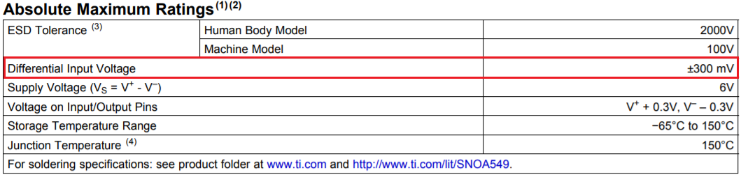
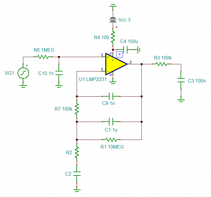
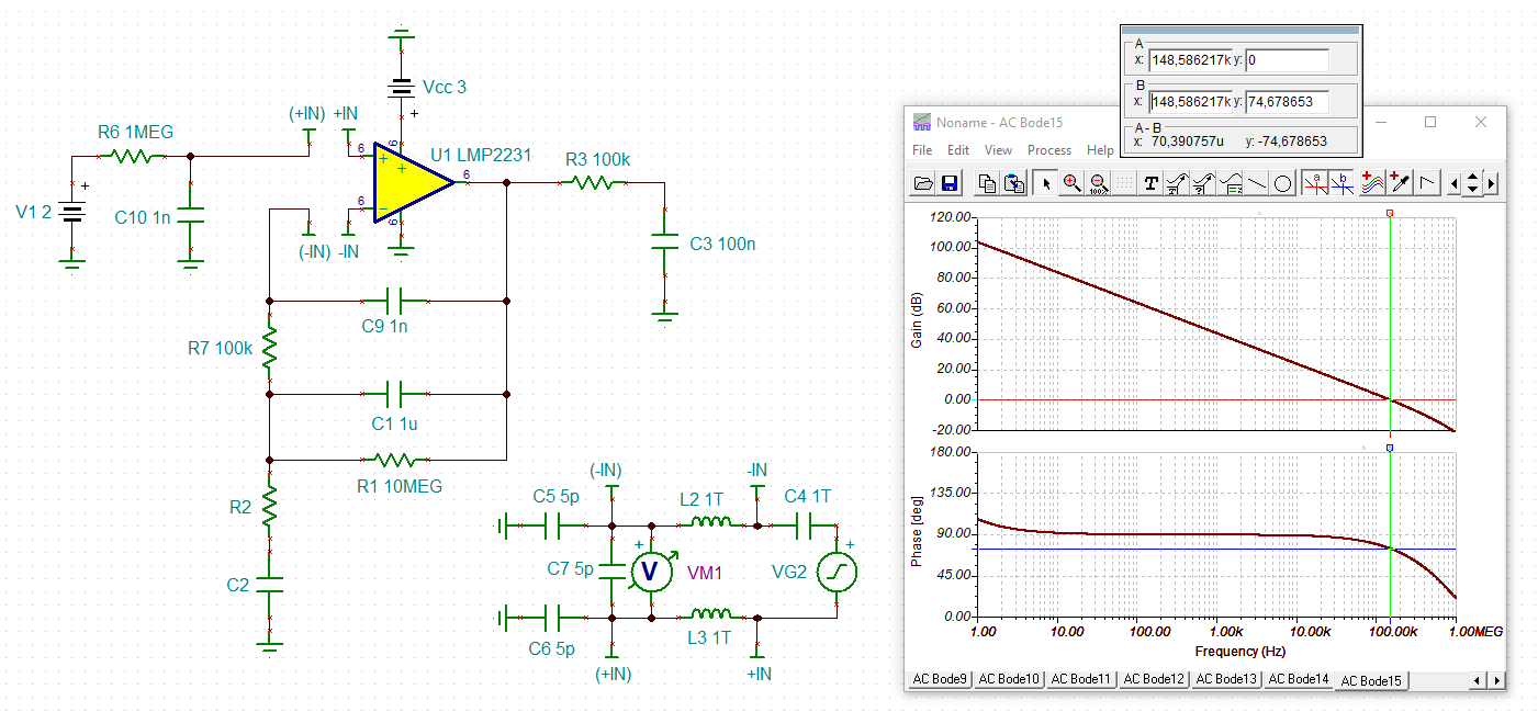
I'm using lmp2231 to buffer the output of a very high impedance electrochemical sensor. The lmp2231 features an astounding low input bias current (femtoamps) and that's what I need to operate the sensor without affecting its chemistry.  When power is removed from the lmp2231, the sensor will continue to apply approximately 1 volt to the lmp2231's non-inverting input which exceeds the Abs Max rating of 0.3 volts. I cannot clamp the sensor with a diode to the positive supply without creating unacceptable leakage current through the diode. However, I am able to put a high value resistor in series with the sensor (for example, 10 Mohms) to limit input current to less than 1 uA. Will this protect the input of the lmp2231? There is insufficient data on the lmp2231 spec sheet to determine whether the lmp2231 incorporates in-circuit overstress protection that can handle a microamp input current if the input voltage exceeds 0.3 volts (above the positive supply).  Many op amps can handle mA overstress currents, but this op amp has such low input bias current that it must have a lower (or even nonexistent) overstress limit.  If there is a TI engineer out there who knows what sort of ESD/EOS protection is on this chip, I'd love to hear from him/her.  

  • Hi Robert,

    LMP2231 has limited built-in ESD protection, but I doubled it that it can handle input current up to nominal +/-10mA in standard op amps. I will ask our expert Thom for this absolute max. current limit, and input voltage limit when the op amp is powered off. 

    High value resistor in series at non-inverting input will certain help, but I am concerned about the thermal noise as shown below. Since this is buffer configuration, the thermal noise may not be amplified significantly, but it can be an unwanted noise source. 

    When LMP2231 is powered off, the chemical sensor's potential can increase up to 1V. What kind of sensor (high impedance sensor) is this? If the sensor's output potential goes to a rest potential, and is unable to source current, then the input may be able to treat it differently. In other words, if the sensor's potential is somewhat floating (high impedance sensor) and potential will collapse when a load is applied. Do you know how much current the sensor is able to source at max. current? It is likely very low, otherwise, you will not use fempto amplifier for the application. 

    If the sensor is low impedance type, then it may be a good idea to place a relay or electronic switch in front of the op amp. If this is the case, I am concerned about the input pin of LMP2231 during the power up sequences, which it may exceed a protection limit momentarily in the part, if the voltage source is presented at the input pin constantly.

    Best,

    Raymond 

  • Hi Robert,

    I don't have detailed information about the LMP2231 input ESD protection circuit. However, I believe it uses a bootstrapped ESD structure that compensates for the otherwise comparatively high leakage currents that would otherwise dominate the 20 fA input bias current.

    TI doesn't characterize op amp products or make any assurances about performance under such conditions as when the supplies turned off and a an input voltage applied. Therefore, I can only provide some discussion as to what you might observe under your particular set of conditions.

    There is a possibility that an ESD structure could become forward biased with the +1 V applied to the input providing a current path can be established to the LMP2231 supply pin. That V+ supply pin would have to be capable of drawing current under the low voltage condition. There will be an ESD diode drop along the path so likely very little current will flow into the V+ pin. I suspect that it will be microamps, and certainly no more than 100 uA, which shouldn't be an issue for the input ESD circuit to handle.

    If you want to provide some additional protection a series resistor is the best solution. I don't think you would need a resistor as large as 10 Megohms. If you figure +1 V at the input and 0.5 V drop across the ESD diode that places +0.5 V at the V+ pin. Even if the series resistor is made 1 Megohm the maximum current would be 500 nA, which isn't going to damage anything. I suspect a 100 k resistor would be suitable.

    Regards, Thomas

    Precision Amplifiers Applications Engineering 

  • Thanks so much for your replies, Raymond and Thom.  

    The question in my original post arose because we had an unexplained failure in a prototype.  The failure occurred with a 100K series resistor between the sensor and op amp.  I can go much higher with that series resistor (e.g., 10 Megs), but I wanted to get as much information as possible from TI before doing any more testing.  

    Raymond, the sensor is proprietary and I'm not at liberty to reveal anything about the chemistry or application.  It is capable of self-generating about 1 volt into a 10 Megohm load for several minutes, and it can supply up to about a microamp into a short circuit for a few minutes.  It is being used in a potentiometric mode, in other words we are trying to draw no current from it at all; that's why we're using the lmp2231. Noise is not a problem because the sensor generates relatively large, slowly varying signals that we are low pass filtering with cutoff frequency << 1 Hz.  BTW, I cannot use a switch or relay to disconnect the sensor.  

    Thom, you raise an interesting question.  Is it possible that during power-down the presence of a sensor output voltage of about 1 to 1.5 volts could turn on the op amp (or an internal protective circuit) so it draws excessive current from the power supply at the point where the supply voltage is at, e.g., 0.5 volts as it is heading down towards zero.  So destructive currrent would be coming from the power supply, not the sensor.  If that is the case, I could easily limit the supply current to a small value with a series resistor in the supply line.  I wouldn't want and probably don't need a bypass capacitor at the V+ pin of the op amp because the circuit is operating at frequencies << 1 Hz and the op amp is driving a high impedance load (> 100K ohms)  My prototype did not have any current limit in the supply line.  

    Your further thoughts and comments are greatly appreciated.

    Thank you,

    Robert Domnitz

  • Hi Robert,

    Comments on your statement:

    "Thom, you raise an interesting question.  Is it possible that during power-down the presence of a sensor output voltage of about 1 to 1.5 volts could turn on the op amp (or an internal protective circuit) so it draws excessive current from the power supply at the point where the supply voltage is at, e.g., 0.5 volts as it is heading down towards zero.  So destructive currrent would be coming from the power supply, not the sensor.  If that is the case, I could easily limit the supply current to a small value with a series resistor in the supply line.  I wouldn't want and probably don't need a bypass capacitor at the V+ pin of the op amp because the circuit is operating at frequencies << 1 Hz and the op amp is driving a high impedance load (> 100K ohms)  My prototype did not have any current limit in the supply line."

    Initially, when an op amp is unpowered just about everything inside it looks like a high resistance between the V+ and V- pins. As the supply is brought up internal bias circuits and current sources begin to turn on and then stabilize at their expected operating levels. Therefore, I don't expect that any of these circuits would high draw enough current to damage the device. However, with some op amps and maybe more so with CMOS op amps, their output transistors may turn on briefly at the same time during power up. During that moment a spike in operating current might occur, but it drops off to normal very quickly as the op amp's internal circuits stabilize to their operating points. That current spike is for discussion purposes maybe 2 or 3x the normal operating, and not nearly enough to damage the device. I don't think that is happening with the LMP2231 so adding a supply current limiting resistor isn't needed.

    If the LMP2231 died after being subjected to multiple cycles where the 1 V input voltage was being applied, then maybe more series input resistance is needed to protect it under that condition.

    We always recommend having a power supply bypass capacitor from both the op amp V+ and V- supply pins to ground. Not only is it intended as charge reservoir when transient events occur, but helps keep the supply line impedance low at higher frequencies. That is important for a number of reasons.

    Regards, Thomas

    Precision Amplifiers Applications Engineering

  • Hi Robert,

    I agreed with Thom's assessment. Perhaps you should place a larger resistor in series with the electrode in order to reduce V+ input voltage. 

    What is your LMP2231's voltage rails? Did you investigate what was damaged in the LMP2231 part. My speculation in this is that the part may be damaged due to larger differential input voltage difference in the application (perhaps you already pointed out, but it was not clear). I would suggest to pay attention of the V+ and V- voltage delta during power on and power off process. 

    My speculation is that your have a potentiostatic electrochemical cell configuration, where LPM2231 is connected to a reference electrode. If the ref. electrode is not inserted in the ionic solution, the ref. cell may not generate approx. 1V potential at the V+ input. I was wondering if you are able to change the test procedures or sequences to avoid the potential conditions, if the 1MOhm or 10MOhm resistors is not working. Just a thought. 

    Best,

    Raymond

  • Thanks, your comments have been very helpful.

    I'm going to do some experimentation and will report back with my results in a few days.

  • Hi Robert,

    what do you want to connect to the output of LMP2231? A digital voltmeter?

    Kai

  • I just want to let everyone know the resolution of my problem.  I determined that overstress of the IN+ input was not the problem.  I put a 1 Meg resistor in series with the sensor output and still had some failures.  The problem turned out to be a result of the long time constant in my feedback RC network.  I was trying to create a very low frequency cutoff (<<1 Hz) using a 10 Meg resistor and a 1 uF capacitor.  Under certain condition, the 1 uF capacitor would have significant charge on it just before I powered down the circuit.  The power-down power supply voltage had a time constant of about 0.25 seconds, so the voltage on the 1 uF capacitor had hardly decayed before the supply voltage went down near zero.  Since the capacitor was connected between IN- and the Output terminal of the op amp, the IN- input was overstressed.  

    To fix the problem, I reduced the feedback capacitor to .033 uF and increased the power supply's output capacitor to slow down the decay of voltage during power-down.  My low frequency cutoff is not as low as I'd like, but I can live with it. 

    The circuit is a little more complicated than what I've described here....in addition to the parallel RC from Output to IN-, there's a series RC from IN- to ground.

    Thanks for your help!

  • Hi Robert,

    thanks for the feedback :-)

    Yes, these caps can carry enough charge to destroy the chip...

    Another dangerous scenario looks like this: If you have a filter cap from the +input of OPAmp to signal ground and accidentally short the supply voltage pin of OPAmp to signal ground with a probe during testing and experimenting, you can easily kill the OPAmp.

    A good measure against this is to add a current limiting resistor between this filter cap and the +input of OPAmp. The inrush current (discharge current) should be limited to under 10mA, better to under 1mA or even less, if the application allows.

    Something similar should work as protection in your circuit as well.

    Do you want to show us your schematic?

    And what do you want to connect to the output of LMP2231, if I may repeat my earlier question?

    Kai

  • The output of the LMP2231 is connected to a cmos input a/d converter through a 100K resistor.

    How can I send you an image of the schematic?

  • Hi Robert,

    You may use the icon circled in red to upload image file, or the icon in green to upload the file. 

    This is a public forum. If you want to privacy, you may request a friendship connection via private E2E message; and I will forward your email to Kai. Or you may send a friendship request to Kai, but I have not tried that options. 

    Best,

    Raymond

  • Hi Robert,

    I would do it this way:

    The phase stability analysis shows a very good phase margin of 75°:

    Kai