This thread has been locked.

If you have a related question, please click the "Ask a related question" button in the top right corner. The newly created question will be automatically linked to this question.

TLV274: short-time that can be withstand between two output

Part Number: TLV274
Other Parts Discussed in Thread: TINA-TI

Hi Team

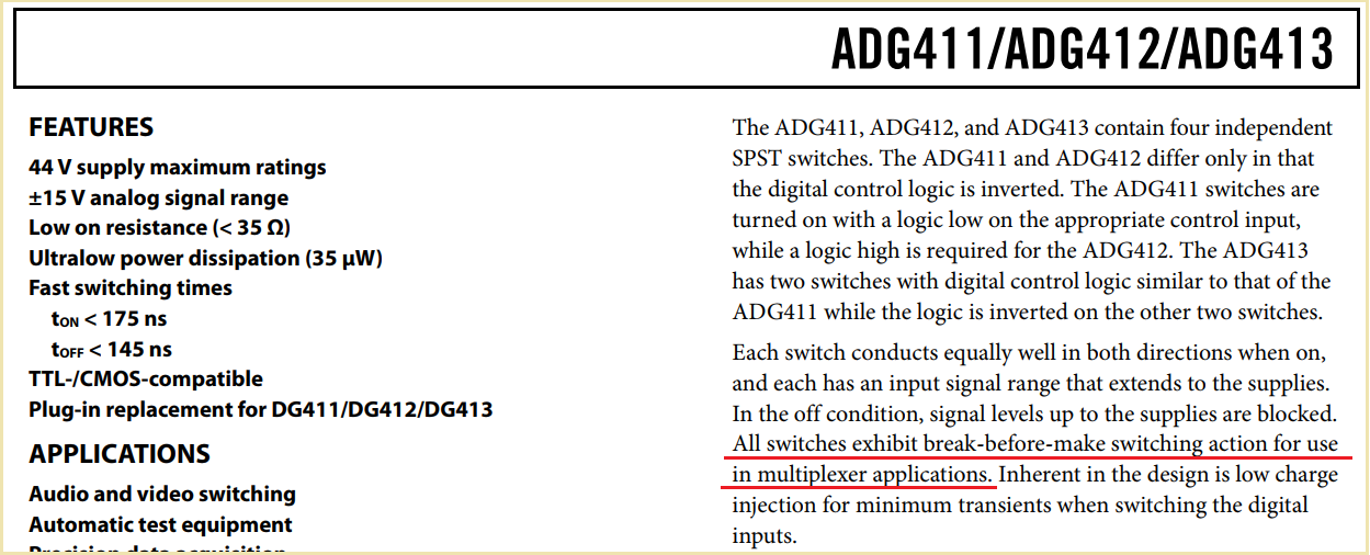
My customer is using TLV274 as voltage follower, with a single power supply of 15V. Its 4 outputs are connected to a multiplexer.

The  multiplexer switches each CH every 250us.

When performing CH switching with a multiplexer, there is a concern that a short circuit may occur between CH during Ton and Toff of each CH.
This can be considered equivalent to short-circuiting the output between the two circuits of TLV274.

In the situation where the above cannot be avoided, please tell us how much short circuit time between OP amplifier outputs can be tolerated (on the order of several us).
The potential difference between 2CH that I'm assuming is
1. Power output range CH1=15V signal and Ch2=0V signal short
2. CH1=5V signal and CH2=0V signal short 

  • Hi Hung,

    the absolute maximum ratings of dataheet specify the maximum output current with 100mA. I would add a current limiting resistor of 75...100R to each output of TLV274. This would not only limit the output current but also isolate the input capacitance of multiplexer and by this stabilize the OPAmp. The multiplexer would furtherly limit the short circuit current by its inherent Ron of switch.

    Can you show a schematic or at least tell what multiplexer you use?

    Kai


  • Former Member
    0 Former Member

    Hello Hung,

    Thank you for your question.  Is the concern that the channels will short within the mux itself or outside of the mux?  I do not understand how this is possible.

    As Kai has asked, do you have a schematic you can share with us?

    Regards,

    Daniel

  • Hi Daniel,

    this can happen, if you have a multiplexer which does not provide "break before make".

    Kai

  • Former Member
    0 Former Member in reply to kai klaas69

    Hi Kai,

    Thank you for pointing this out as I'm not very familiar with multiplexer specifications.

    It will be good to see the schematic either way.

    Regards,

    Daniel

  • Hi Kai, Daniel 

    Thanks for your reply. 

    I am asking the customer if he is able to provide the schematic or the information of MUX he's using.

    I would like to confirm with the sentence below that Kai mentioned, 

    could you kindly explain how the current limiting resistor helps to isolate the input capacitance of multiplexer?

    I mean, how does the current limiting resistor relates with the input capacitance of multiplexer.

    Sorry for the lack of knowledge about this.

    "I would add a current limiting resistor of 75...100R to each output of TLV274. This would not only limit the output current but also isolate the input capacitance of multiplexer and by this stabilize the OPAmp. "

  • Hi Hung,

    this is very nicely explained in the TI's stability training video series:

    Kai

  • Former Member
    0 Former Member in reply to Hung Ching Hsu

    Hi Hung,

    The series pointed out by Kai is quite helpful.  Part 5, which is linked, speaks directly about the technique called the "Isolation Resistor."  However, the previous videos are also good for understanding how instability occurs and why it is sometimes needed to begin with.

    Regards,

    Daniel

  • Hi Kai, Daniel 

    Thanks for your information for the "Isolation Resistor." I'll check it.

    The customer is using the ADG411 multiplexer from ADI. 

    (According to the customer's word, although it mentioned "break-before-make" in the datasheet, ADG411 doesn't have the function. The performance should be considered the ton and toff when single power supply)

     The Ron of ADG411 varies from 40-100 ohm. 

    I would like to send the schematic to you two in private.

    For Daniel, I searched up your mail address so I will send it directly to your mailbox.

    But for Kai, could you kindly provide your mail address, or can I send the file to you via E2E?

    I am unfamiliar with it, I pressed the +Connect bottom on Kai's page anyway.

    Maybe I can send you after you accept my +Connect request.

    The customer said he doesn't want to add any current limiting resistor that Kai mentioned for 2 reasons.

    1. Already many pull-down resistors before and after the part of the schematic 

    2. it may have an influence to the device power sequence. 

    Regarding to above, I think the worst case for current when two of TLV274 is shorted will be that, (15-0)V/(40+40)ohm=187.5mA.

    (15-0)V : (largest voltage difference between two TLV274)

    (40+40)ohm : Smallest Ron series with two switch

    Since it exceeds the max rating current(100mA) for TLV274, so I think TLV274 may not work for this case.

    Is there any other possible way to prevent the high short current?

  • Former Member
    0 Former Member in reply to Hung Ching Hsu

    Hello Hung Ching,

    Thank you for replying privately.  I will respond to you on e2e.  You may reach out again via email if you would like.

    I'm not sure why adding a resistor to the output of the amplifier would potentially disturb the desired power sequence.  Interestingly, one of my colleagues made the exact same suggestion as Kai, to add a 100Ohm resistor at the output of the amplifier.

    I'm also not sure that the 40Ohm impedance of the mux switch would still be valid under the temporary short condition.  After all, it is not an expected condition and not described in the data sheet.  Many, if not all, of our newer amplifiers will have short circuit protection such that, at a certain output current, the output stage limits itself from any further current output.  There's no mention of this in the data sheet of the TLV274 and the part is quite old.  So, I'm not sure whether that is the case for the TLV274 and I don't think it is from the data sheet.

    If the customer cannot be convinced to place any external components, then I would think the only solution would be to switch to a true break-before-make mux.  They can also switch to an amplifier that has an output short circuit current limit in the data sheet, although I think this approach would be less optimal as it does not directly solve the issue.

    Please let me know your thoughts.

    Regards,

    Daniel

  • Hi Hung,

    I have sent you a message :-)

    Kai

  • Former Member
    0 Former Member in reply to Former Member

    Hello Hung Ching,

    Since you're still waiting to hear back from the customer, I will go ahead and mark this thread as resolved for now.  You can come back and ask another question here, if needed.

    Regards,

    Daniel

  • Hi Daniel 

    Thanks for your support. 

    Although I haven't gotten reply from the customer about the previous question, the customer is asking another question about TLV274.

    The customer is using RC-LPF at the output of TLV274, he wants to know if it works for phase compensation.

    If yes, could you recommend the capacitor value which could be stable enough?

    Please let me know if you need other information to answer this question.

  • Hi Hung,

    the ADG411 is a break-before-make mux:

    So there should not be any issue with your circuit.

    Also, there should not be any stability problem with the TLV274. The maximum capacitive load in your circuit would be 62pF. Even with this load capacitance the TLV274 looks very stable:

    hung_tlv274.TSC

    See also figure 16 of datasheet of TLV274 showing a phase margin of 70° :-)

    Kai

  • Former Member
    0 Former Member in reply to Hung Ching Hsu

    Hello Hung Ching,

    I agree with Kai.  It should not be difficult to keep the amplifier in a stable region in this case.

    Do you know what cutoff frequency the customer would like?  I would think it would be best keep the resistor value lower and the capacitor value higher to avoid undesired voltage drops across the resistor.  This is ok so long as the amplifier is kept stable and I can verify this for you once the values are picked.

    Regards,

    Daniel

  • Hi Kai 

    Thanks for your reply.

    I confirmed with the customer but the customer said ADG411 seems don't have break-before-make function.

    So to confirm the phase margin, I could just simulate in TINA-TI. Sorry to ask such a simple question.

    And I would like to know why you use 62pF here as an example, since I didn't find the value after looking up in datasheet of TLV274 and other components.

    BTW, I answered to the customer and maybe I can simulate by myself when I get the capacitor value he wants to use. 

  • Hi Hung,

    regarding the break-before-make issue I see no reason to doubt the datasheet of ADG411. Eventually the customer might want to contact AD directly?

    62pF is the maximum load capacitance which one of the four TLV274 sees due to the parasitic capacitances of the drain and source pins of ADG411. 9pF on each side of an opened switch and 35pF on a closed switch gives 3 x 9pF + 35pF = 62pF.

    Feel free to contact us when you want to have support with the phase margin simulation :-)

    By the way what IC are we talking about? IC145 or the other OPAmp in the schematic?

    Kai

  • Former Member
    0 Former Member in reply to Hung Ching Hsu

    Hi Hung,

    Here is the circuit you'll want to use to check stability.  Just change the load as necessary.  Then hit "Analysis" -> "AC Analysis" -> "AC Transfer Characteristic".  Once the sim runs, you can right click on the gain plot and find the phase margin of the circuit.  Generally we recommend more than 60 degrees of phase margin for stability.

    7181.hung_tlv274.TSC

    Regards,

    Daniel

  • Hi Kai 

    The customer contacted with ADI and it seems ADG411 doesn't have that function.

    Thanks for explaining where 62pF of capacitor comes from. 

    We are talking about IC145.

    Thanks for your help. I'm still waiting for response from customer. 

    I'll let you know if I have another question.

  • Hi Daniel 

    Thanks for your information for phase margin. 

    I tried the file that Kai provided and it looked no problem.

    And I also forwarded the information you told me for resistor and capacitor selection to the customer last week. 

    Since I haven't got response from the customer, I'll let you know if there's any updates.

  • Former Member
    0 Former Member in reply to Hung Ching Hsu

    Hello Hung Ching,

    Sounds good.  Please let me know if there is anything else I can do to help you or your customer.

    Regards,

    Daniel