This thread has been locked.

If you have a related question, please click the "Ask a related question" button in the top right corner. The newly created question will be automatically linked to this question.

INA181: Low Side negative Current sense issue

Part Number: INA181

I'm using INA181- A1 device for my Low side Leg current sensing.

My Circuit looks like this,

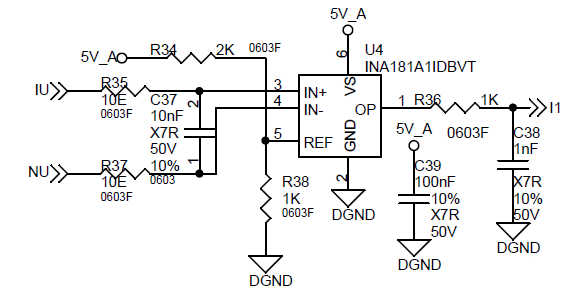
I'm using 2m ohm Sense resistor and my maximum current is 16 A. The Op-amp gain is 20.

The op-amp output is good at positive cycle, But in negative cycle the sine gets distorted and missing negative cycle.

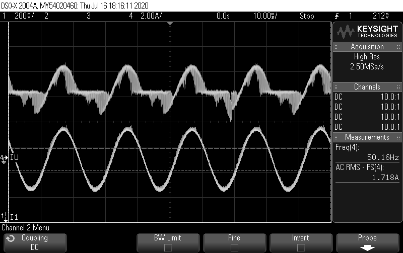
The top waveform is amplifier output. the bottom one is the Actual current output.

What can go wrong in this current measurement?

Please help me solve this issue.

Thanks,

Kumar V

  • Hi Kumar,

    not knowing whether this is the cause, but you should drive the REF pin low ohmically. Use a buffer as shown in figure 53 of datasheet.

    Kai

  • Dear Kai,

    I have done that too. Now the offset is 1.66 V and i have lowered the resistance value as you said.

    But still i am getting the same waveform. The frequency of the current is 8 khz-20 khz.

    Thanks,

    Kumar V

  • Hi Kumar,

    is the measuring current a pure AC current?

    Kai

  • Hey Kumar,

    Thanks for considering to use Texas Instruments.  Can you tell me what your common mode is?  If you are using a function generator to generate the differential and have not provided an offset above zero, I could imagine you might see a waveform like this.  I suspect the ESD structure could be distorting the signal.  If this is not your issue, I think you may need to look at your supply line and see if it is stable.  Then if that is stable, we might need to do some continuity tests between your probe points and the device pins to check for soldering issues.

  • Hi Patrick Simmons,

    Thanks for your reply.My common mode is between the sense resistor of 2m ohm. The maximum current through the sense resistor is 16A. The supply is stable as you could see the bottom waveform is the actual current which is pure sine wave. I'm using 10E resistor in series with 10nf cap filter as mentioned in application note for filtering. What it would cause the negative cycle alone to distort?

    Please help me in this regard..

    Thanks,

    Kumar V

  • Dear Kai,

             Yes,it is a purely sinusoidal AC wave.Simply, it is a leg current of an inverter which runs an induction motor in V/F method in which the output to the motor is purely sinusoidal and we are measuring it in the bottom (leg)of the inverter.

    Please help me to sort out this issue.

    Thanks,

    Kumar V

  • Hello Kumar,

    You need to show me the IN+ voltage relative to ground and the IN- voltage relative to ground.  Your common mode voltage will be ((IN+)-(IN-))/2.  Once I see that, we can rule that out.

  • Hi Kumar,

    can negative spike voltages be superimposed to the signal from time to time, something like inductive kick backs? Or by other words, could the INA181 be damaged? Can you take a fresh INA181 and check again?

    Kai