This thread has been locked.

If you have a related question, please click the "Ask a related question" button in the top right corner. The newly created question will be automatically linked to this question.

LM311: Amplifiers forum

Part Number: LM311

Dear,

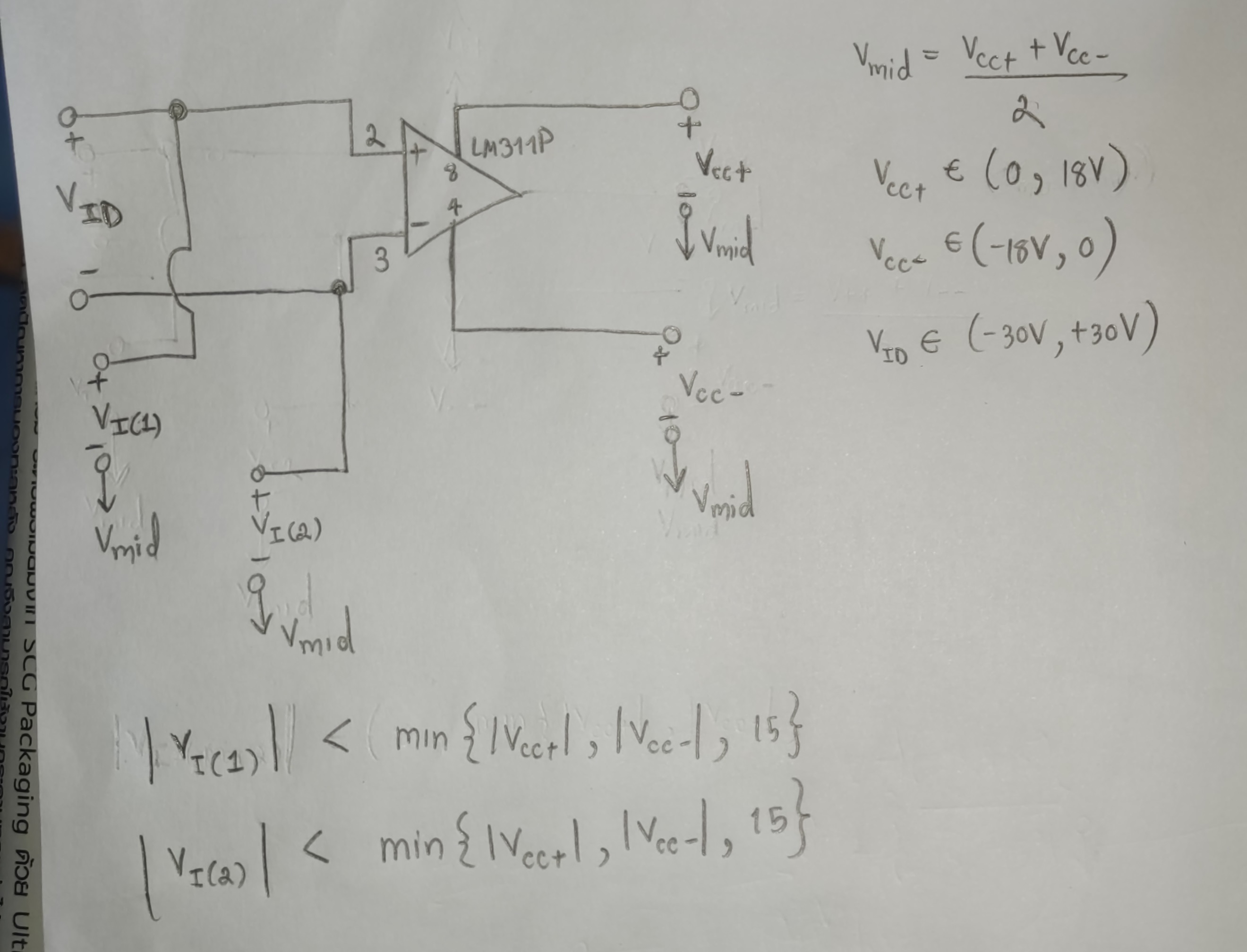
Please find the attached picture and the datasheet https://bit.ly/30m9fQl. I have read the datasheet, and I am curious about the voltage range of each pin. This is because almost all voltage ratings are measured with respect to the midpoint of Vcc+ and Vcc- (See note 2 on page 4). I am not quite familiar with this.
So, I listed out a possible range of each voltage. Could you please check if my interpretation is correct or not?

In Figure 25, it seems that Vcc+ and Vcc- are referred to the ground (negative pin of the comparator), not their midpoint. So I am curious if the definitions of these Vcc+ and Vcc- are the same as those mentioned in the absolute maximum rating?

Sincerely,
Nattapong Chotikorn
  

  • Hi Nattapong,

    this is too complicated for me :-)

    What supply voltages do you want to use? What is your input voltage range? And what load do you want to drive?

    Can you post a schematic?

    Kai

  • Hello Nattapong,

    Yes. The input voltage are referred to "GND" (midpoint of the supplies) in the tables.

    The LM311 is specified with +15 and -15V "split" supplies, both positive and negative. Though it is possible to use it with a single supply.

    So the input voltages are in reference to ground. Since the LM311 was specifically designed to interface between split supply, bipolar analog circuitry and single supply, ground referenced digital logic.

    So on "split" +15V and -15V supplies, you can apply -14.5V to +13V to the inputs according to the table.

    In Figure 25, the input is grounded - so the input range is 0V, or 15V above V-. The other input can go -14.5V to +13V from there.

    If you want to run it on a single supply, say +12V, then you have to convert the input range to single supply by finding the difference between the limit and the nearest rail.

    For the lower limit, the spec is -15V supply and -14.5V limit. This results in the limit being 0.5V above V-.

    For the upper end, with a +15V supply and +13V limit, results in the limit being -2V below V+.

    To convert to single supplies (V- at GND), you take these values from the total supply voltage to get the total input range.

    +12V -2V = +10V upper input limit.

    0V + 0.5V = +0.5V lower input limit.

    The 12V single supply input range is +0.5V to +10V.

    If you were running on a +6 and -6V "split" supplies, then the input range would be -5.5 to +4V.