This thread has been locked.

If you have a related question, please click the "Ask a related question" button in the top right corner. The newly created question will be automatically linked to this question.

BOOSTXL-AFE031-DF1: PLC TX/RX verification

Part Number: BOOSTXL-AFE031-DF1
Other Parts Discussed in Thread: LAUNCHXL-F280049C, , AFE031, C2000WARE, AFE032

Hi Support,

I got BOOSTXL-AFE031-DF1 paired with LAUNCHXL-F280049C and want to test send/receive over 2 board sets. According Transmitter Serial Commands on page 14 of the BOOSTXL-AFE031-DF1 User's Guide, there's no packet/message send command. So how to set up to send a message with the  example code boostxl_afe031_f28004x_dacmode? And is there any example code that will work with zero configuration gui? Hopefully, I would like to test SNR and try OFDM too. Please advise.

Thanks advance,

Eric

  • Hi Eric,

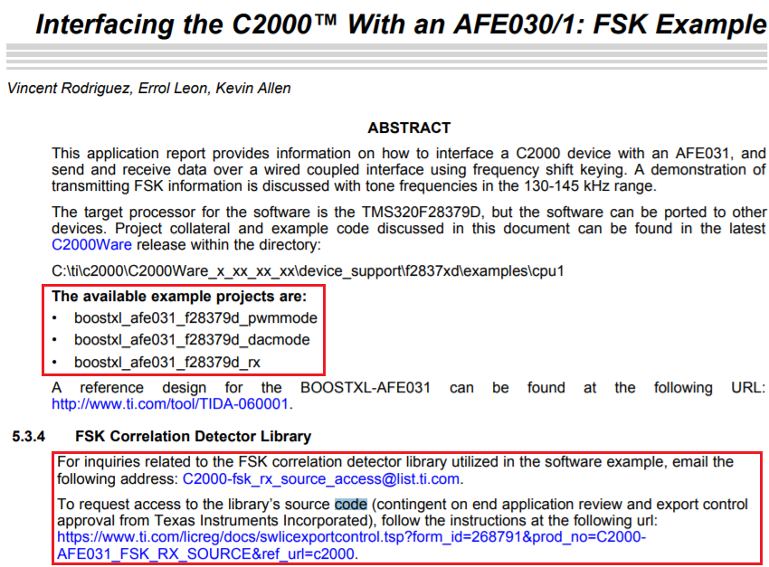
    Please check out the following application note. Please let us know if we have any questions.

    https://www.ti.com/lit/an/sprac94c/sprac94c.pdf

    https://e2e.ti.com/support/amplifiers/f/14/p/877641/3248759#3248759?jktype=e2e

    Best,

    Raymond

  • Hi Raymond,

    It has example codes boostxl_afe031_f28004x_dacmode/pwmmode/rx under the folder of c2000\C2000Ware_3_02_00_00\device_support\f28004x\examples\ for F280049C, not sure why need to port from f28379d's version. My question is do you have any example code that can work with zero configuration gui? I tried with dacmode and rx example codes with LAUNCHXL-F280049C, but it only worked (in test mode) less than 10 meters when connected to AC, even setting mark and space gains to max(999). Please advise.

    Thanks,

    Eric

  • Hi Eric,

    I do have another AFE031 GUI and it has to be installed. Again, it is similar to sample code, except it does not require to program or compile the code.  What do you mean by "Zero-configuration GUI"? 

    I think that the sample code will work more than 10 meters. It is configurable. To transmit in longer distance, you have to increase the Tx Gain, increase the output amplitude, perhaps changing the current limiting features etc.. 

    I assumed that you are coupling onto AC power line. What is the AC frequency? This demo is capable to transmit and receive over AC powerline as well as DC powerline. 

    Please provide me with your design requirements, and I will see what to change in order to meet your requirements. 

    Not all codes are compatible due to long history of C2000 MCUs. If you want to know the details, I have ask a MCU engineer to help you out. Or you can submit E2E questions over C2000 group, if you want to have an answer. 

    We do not have a complete application GUI that will explore all the features in powerline communication. The same codes in the link (previous reply) are the majority of it. There are some other sample code in OFDM modulation/demodulation codes are managed by other sw group (address AFE032 IC). The sample code is mainly for FSK or BSFK transmission protocol (address AFE031 IC). 

    Best,

    Raymond

    Best,

    Raymond 

  • Hi Raymond,

    The Zero Configuration GUI is an application described in static5.arrow.com/.../tidu237.pdf
    Yes, as I mentioned previously, I had tried to increase the TX gain to 999, and got a Vpp around 5V. Is that the expected value?

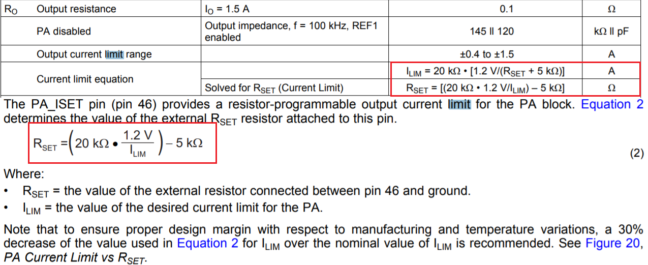
    How to change the current limiting features?

    Yes, I tested with coupling on 110V (60Hz) AC power line.

    Thanks,

    Eric

  • The Zero Configuration GUI is an application described in static5.arrow.com/.../tidu237.pdf

    I need to get you on this. I have to ask our software engineer for the download. 

    How to change the current limiting features?

    See the image below. You may connect a load resistor at the output of AFE031's amplifier, and verify the current limit. 

    Regarding to AC powerline coupling, can you tell me the type of transformer that is used and model number? Which application note or reference design did you use? I can help you to resolve the issue tomorrow. 

    Best,

    Raymond

  • Hi Raymond,

    I did download and install the ZCG, but the issue is where to the example code (F280049C version) in order to talk to the application.

    As far as I understand, the current limiting is most likely for the protection, not able to maximize the transmit distance.

    Here's the schematic that I followed to build my coupling circuit:

    So, except to increase the Gain of the amplifier by software, what other approaches can be used for increasing the transmit distance?

    Thanks,

    Eric

  • Hi Eric,

    Please click on the icon circled in red to upload a image file, click on the icon circled in green to upload a standard file. 

    I'd like to take a look at the schematic and components used in the Tx and Rx powerline. AFE031 has plenty power to transmitter 1000' or more. However, it wrong components are used in coupling with the AC powerline, Tx power losses can be very significant. For instance, the transformer used to couple the Tx signals over the powerline. If wrong transformer type is used, the transformer's magnetic core loss can be very high, and Tx signal is not going to transmit very far. 

    Best,

    Raymond

  • Hi Raymond,

    Oops, sorry for the issue with the image Snapshot.

    Again, here's the schematic. Note that inductor L2 600nH is populated.

    https://www.ti.com/lit/ug/tidu262/tidu262.pdf?ts=1596037623793&ref_url=https%253A%252F%252Fwww.google.ca%252F

    Thanks,

    Eric

  • Hi Eric,

    Thanks for the information. We have several different kits, that is why I am asking. 

    The T1 has Np: Ns = 1.307:1. which means if you have Vpri = 10Vp-p (Pin 1-4), you will have Vsec  7.65Vp-p at pin 8 and pin  7. C1 capacitor is used to block DC, transmit AC signal. 470nF has impedance of 1/sC = 1/(2*pi*f*C) = 2.26 ohm at 150kHz. The 600nH will have impedance in sL=1.768 Ohm at 150kHz. But I do not believe that this is your issue currently. 

    At Tx side, you mentioned you have sine input signal with 5Vp-p amplitude (because you have been increasing the gain). I believe that power amplifier (PA) supply voltage is 15V and ground. The PA on its own has a fix gain of 6.5V/V. With 15V PA supply rail, the max. peak output voltage swing is approx. 13V.

    Let us assume PA's Vo = 12Vp-p, with a fixed 6.5V/V gain, the input should be 12V/6.5 = 1.846Vp-p. If the input is 5Vp-p at PA_IN, the output will be 5V*6.5= 32.5Vp-p, which it exceeds the PA_Supply range.

    With single voltage rail, the common mode voltage Vcm is configured at the mid point of PA_Supply rail or 7.5Vdc. In Vo=12Vp-p case, the sine's max. output voltage swing will be 7.5V+6V=13.5V and sine's output valley will be 7.5V-6V=1.5V. 

    Please control PA-IN with sine amplitude approx 1.5Vp-p, which it will generate Vout swing at approx. 10Vp-p.

    Yes, AFE031 has many gain controls in Tx and Rx, which they are great for analog programmability. At the same time, it adds some complexity in the configuration. 

    If you have have additional questions, please  send me some scope shots about your issues, if you are able. This will help me to see the possible issues. 

    BTW, AFE031's nominal gain of 6.5V/V is AC gain, since PA's input is AC coupled in Cin, see the above image. 

    Best,

    Raymond

  • Hi Raymond,

    1. I think the impedance of the 600nH at 150KHz should be 0.5652 Ohm. But anyway, what is the  impedance restriction of those components? If I want to do 3-phase coupling, how to choose the inductor (shared?) and capacitors?

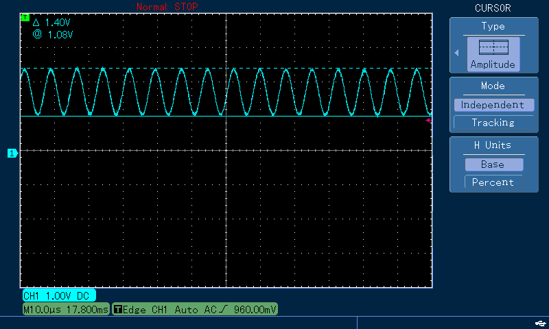
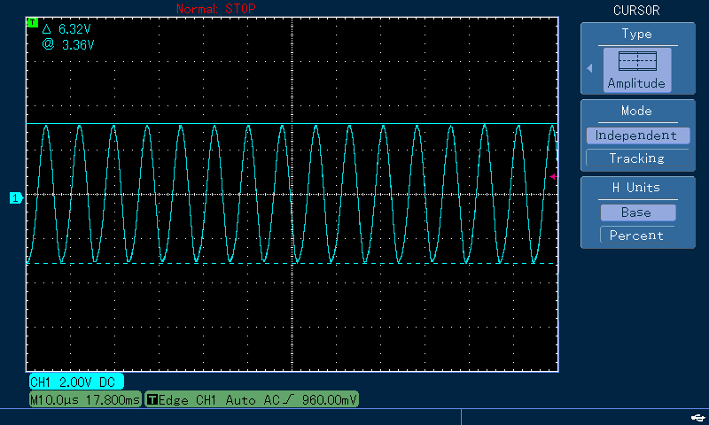
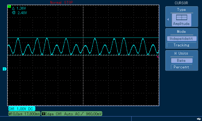
    2. The sinewave signal with 5Vp-p amplitude I mentioned previously is a signal measured on PA_OUT. I re-tested it and made some screenshot below:

     Signal on PA_IN at Mark tone Gain m=960

     Signal on PA_OUT at Mark tone Gain m=960

    So the Gain of PA should be 6.32/1.4=4.5 but not 6.5?

    And when the gain is increased to m=970, something strange is shown up on PA_IN:

    So not able to reach 1.5Vpp on PA_IN. BTW, I am using 12V adapter for power supply, but I don't think that's something related.

    3. Do you have any example code that combined Tx and Rx together (duplex communication) for F280049C?

    Thanks,

    Eric

  • Hi Eric,

    1. I think the impedance of the 600nH at 150KHz should be 0.5652 Ohm. But anyway, what is the  impedance restriction of those components? If I want to do 3-phase coupling, how to choose the inductor (shared?) and capacitors?

    yes, 600nH at 150kHz has impedance approx. 0.5655 Ohm. Higher impedance at higher frequency, the signal attenuation is going to be more, but it should not be significant for short distance data transmission. I^2R is still the loss across the given components. 

    Ok, you'd like to transmit modulated signal over 3-phase power system. Since the 3-AC power line goes together in a wire bundle, you may need to send the modulated signal over one phase. Please tell me more about your application. 

    Since AC phase is 120 degree apart over 3-phase AC lines, the transmitter modulated signal can be trickier. Let me give you an example.  A typical household is wired in 2-phase electrical outlet (Phase A and Phase B). If one places a transmitter modulated signal in Phase A powerline, all power outlets or connection associated with the outlet in a house or building in Phase A will be transmitted/received. Because  of high impedance connection from Phase A to phase B, no modulated signal can be transmitted or received via Phase B power line. The similar dilemma will exist in 3-phase power line. 

    2. So the Gain of PA should be 6.32/1.4=4.5 but not 6.5?


    You need to measure PA_IN after the capacitor coupling (not before). Since your PA_in plot has is displaying on top of ground, I think that you measured the PA_in before the capacitor. It should be pretty close to 6,5, since PA has the max. gain error of +/-1%. 

    So not able to reach 1.5Vpp on PA_IN. BTW, I am using 12V adapter for power supply, but I don't think that's something related.

    If your power adapter or DC voltage to PA is 12V, the PA's max. Vout swing will be approx. 10V, see Output specification on p.10 of the datasheet.

    3. Do you have any example code that combined Tx and Rx together (duplex communication) for F280049C?

    AFE031 is specified to perform half duplex data transmission mode. One node transmits and other nodes are listening or vice versa, but not Tx and Rx at the same time. It is similar to handheld portable radio or walkie talkie (land line telephone is working in full duplex mode). Can we make the PLC in full duplex mode? The answer is maybe, but I have not tried. We can talk about it if you are interested. 

    Best,

    Raymond


  • Hi Raymond,

    1. Please tell me more about your application.

    We are going to develop a system for lighting control via inline communication. Lights can be installed on any phase of power line, and will need with repeater feature.

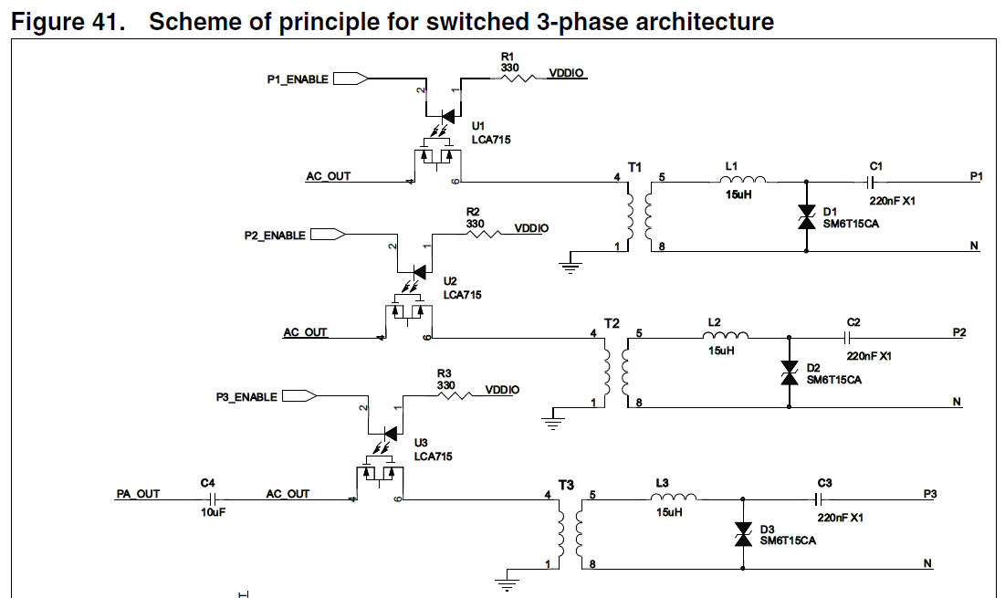
    As far as I know, there are 2 architectures for 3 phases coupling:

    Looks the locations of Inductor and capacitor are switched comparing to TI suggestion, is that critical?

    For the non-switched mode, how to choose the inductor and capacitors if the same transformer (750510476) is used? 

    2. So not able to reach 1.5Vpp on PA_IN

    I retested the signal of PA_IN (pin18 of U1), it's Vpp=0.92V. Basically the gain is around 6.5V/V. But the question is: how to increase to 1.5Vpp? Looks 1Vpp is the maximum I can reach.

    3.1 Current example code only set up 2 frequencies Mark and Space. Do you mean it is not able to set up more (for example Mark2 & Space2)?

    3.2 Do you have example code combining tx/rx function in one project file?

    Thanks,

    Eric

  • Hi Eric,

    Looks the locations of Inductor and capacitor are switched comparing to TI suggestion, is that critical?

    For the non-switched mode, how to choose the inductor and capacitors if the same transformer (750510476) is used? 

    It looks about right. The objectives are to couple high frequency signals onto the AC power line with the minimum amount of power loss and maximize the transmission signals' amplitude. I think that you are right. Either you capacitive coupled or transformer coupled onto the powerline. The modulated transmission signal may be the same in this case (does not have to), you have to treat each phase independently. Let me think about if there is a better way to couple onto 3-phase powerline. 

     2. So not able to reach 1.5Vpp on PA_IN 

    You may have to increase the PA's power rail to 15Vdc (this will help the output voltage swing). In addition, you need to increase the amplitude of DAC output --> that will help. After DAC, there is a low pass filter to smooth out the sine wave (assume that you are using the DAC-mode). You may have to reduce the value of resistor (LPF's resistor), and decrease the capacitor value to achieve the same cutoff frequency. If you play around DAC and input value, you may be able to increase the Tx amplitude to PA. Use large capacitor value to couple the transmission frequency. 

     3.1 Current example code only set up 2 frequencies Mark and Space. Do you mean it is not able to set up more (for example Mark2 & Space2)?

    You may be able to setup another sets of "0" and "1" in the powerline. One set is responsible for Tx, and other set is responsible to Rx. I have not simulate it, but I think that it may work. The problems are your modulated signals may be more complicated. You may need fast MCU to dempdulate the incoming signals and perform fft accordingly.

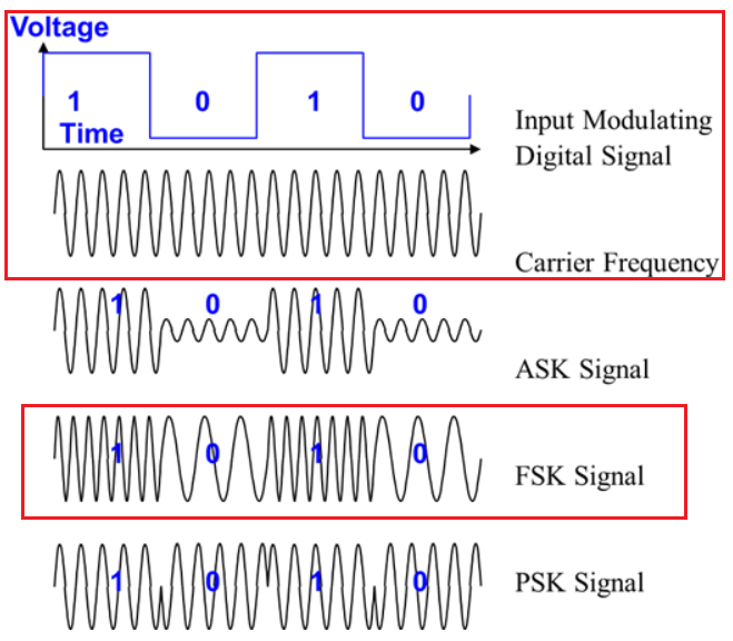
    What is required kbps transmission speed you are looking for. For lightning application, I assumed that it does not need to be fast. FSK or BFSK modulation protocol may be adequate. 

     3.2 Do you have example code combining tx/rx function in one project file?

    Application and SW engineers are separate groups and in different locations in this case. Let me ask them what they have next week. 

    Best,

    Raymond

  • Hi Eric,

    If you have not downloaded AFE031 codes from the following site, please sign in and request for the source code access. 

    https://www.ti.com/licreg/docs/swlicexportcontrol.tsp?form_id=268791&prod_no=C2000-AFE031_FSK_RX_SOURCE&ref_url=c2000

    If you have any additional questions, please let me know.

    Best,

    Raymond

  • Hi Raymond,

    Looks the example codes are from C2000Ware, but not combining tx/rx function in a single project.

    Previously you mentioned that AFE031 is specified for half duplex, so does it support mesh network? According the datasheet, it does support G3. Do you have example code for it (or even AFE032)?

    Thanks,

    Eric

  • Hi Eric,

    Looks the example codes are from C2000Ware, but not combining tx/rx function in a single project.

    If the SW has Rx sample code, it should have Tx code to send data in order to receive code. I have done any programming in C2000 PLC application, but I can help you to write it, if this is what you are looking for. In frequency shift keying (FSK) modulation, Tx is sending a frequency that is represented "1" and another frequency that is represented "0" over the powerline. 

    AFE031 has two modulation methods: 

    1. DAC-mode:  Use DAC to convert digital signal to modulated AC frequency through a LPF (this example should be in C2000Ware). 

    2. PWM-mode: Use phase offset PWM signals to go through sets of LPFs to generate sinewave transmitted signals. 

    You mentioned that AFE031 is specified for half duplex, so does it support mesh network?

    AFE031 Tx and Rx signals are broadcast over the entire network that is connected to a powerline (AC or DC powerline), as long as there is an impedance path (say 150kHz impedance path) to each node and the impedance is not attenuate the transmission signals significantly. For AC powerline coupling application, it means that the high frequency signals can transmit through the powerline with a same AC phase in a house or building etc.. If there is an AC socket in house or building with different AC phase from the power ine, the high frequency signals can not transmit through, because there is no impedance path or high impedance path from one AC phase to a different AC phase in the powerline. 

    According the datasheet, it does support G3. Do you have example code for it (or even AFE032)?

    Yes, AFE031 and AFE032 are suporting G3, PRIME and other communicaiton standards. AFE032 is higher BW PLC controller which it has full BW up to 700kHz. AFE031 has full BW up to 300kHz. Both AFE03x belongs to Narrow Band-PLC (NB-PLC) category, which is <500kHz. Transmission BW>500kHz is considered Broadband.-PLC or BB-PLC. 

    https://www.ti.com/tool/TI-PLC-G3-DC?keyMatch=TI%20G3%20POWER%20LINE%20COMMUNICATION%20DEVELOPERS%20KIT%20DESIGN&tisearch=Search-EN-everything

    We may not have an integrated software package that contains all the sample codes. Yes, sample codes are written in different models of C2000 MCUs that are supported by required processors and communication protocols. 

    Please let me know if you have further questions. 

    Best,

    Raymond