This thread has been locked.

If you have a related question, please click the "Ask a related question" button in the top right corner. The newly created question will be automatically linked to this question.

PGA113: PGA113:The output waveform cannot be amplified

Part Number: PGA113

The timing diagrams of CLK, CS, and DIO of PGA113 are correct, and the related pin connections are okay, but pga113 cannot be amplified. The default magnification of input 0x2a50 is 1. I don’t know the reason?

#define PGA_SET_SCL() GPIO_SetBits(GPIOI, GPIO_Pin_2) // PI2-> U3_sclk
#define PGA_CLR_SCL() GPIO_ResetBits(GPIOI, GPIO_Pin_2)

#define PGA_SET_CS() GPIO_SetBits(GPIOI, GPIO_Pin_0) // PI0-> U3_cs
#define PGA_CLR_CS() GPIO_ResetBits(GPIOI, GPIO_Pin_0)

#define PGA_SET_DIO() GPIO_SetBits(GPIOI, GPIO_Pin_1) // PI1-> U3_dio
#define PGA_CLR_DIO() GPIO_ResetBits(GPIOI, GPIO_Pin_1)

void PGA113_Write(u16 ads_dat) //MODE 1.1
{
unsigned char i;
PGA_SET_CS();
PGA_SET_SCL();
PGA_CLR_CS();
DELAY(0x100);
PGA_CLR_SCL();
DELAY(0x100);
for(i = 0; i < 16;i++)
{
PGA_SET_SCL();
if(ads_dat&0x8000)
PGA_SET_DIO();
else
PGA_CLR_DIO();
DELAY(0x100);
PGA_CLR_SCL();
ads_dat <<= 1;
DELAY(0x100);

}
PGA_SET_SCL();
DELAY(0x100);
PGA_SET_CS();

}

int main(void)
{

PGA113_Initiate();

while(1)
{

PGA113_Write(0x2A40); //0x0010 1010 0100 0000

}

}

Yellow is SCLK, blue is DIO.The output waveform cannot be amplified,why?

  • HI Shike,

    Looking at the oscilloscope capture plot, it appears you are using SPI Mode 1, 0 (CPOL=1, CPHA=0 which is incorrect (the SDIO appears to be changing state on the rising edge of SCLK). (Corrected 7-21-2020)

    The serial interface diagram of Figure 56 of the PGA113 datasheet shows that the device only supports SPI Mode 0, 0 (CPOL=0, CPHA=0) or SPI Mode 1, 1 (CPOL=1, CPHA=1). 

    Please change the phase in your SPI settings for CPOL=0, CPHA=0 (or alternatively to CPOL=1, CPHA=1). 

    If after changing the SPI settings, issues continue, please provide a zoomed-in oscilloscope capture of one frame including CS, SCLK, DIO; and the command you are writing.

    Thank you and Regards,

    Luis  

  • HI Shike,

    Looking at the oscilloscope capture plot, it appears you are using SPI Mode 1, 0 (CPOL=1, CPHA=0) . (Corrected typographical error 7-21-20)

    Can you please change the phase on the SPI settings?

    Can you please zoom in the oscilloscope capture and include CS on the oscilloscope capture?

    Thank you and Regards,

    Luis  

  • I have changed to falling edge trigger, but the waveform is still not amplified, why? Can you provide some possible ideas?

  • CPOL = 0,CPHA = 0;CPOL = 1,CPHA = 1;What do CPOL and CPHA specifically refer to?

  • Shike,

    The correct serial clock polarity (CPOL) and clock phase (CPHA) in the Serial Peripheral Interface (SPI) settings are required and fundamental to communicate properly with a SPI compatible device.  The PGA113 is compatible with the SPI interface, and accepts mode 1,1 (CPOL=1, CPHA=1) or mode 0,0 (CPOL=0,CPHA=0). 

    Please take a careful look at Figure 56, and notice how the DIN and DOUT data updates with respect to the SCLK falling edges. 

    Notice on Figure 56, the DIN data is stable at the rising edge of the SCLK edge and the SDI data updates or changes on the falling end of SCLK.  Therefore, the PGA113 device captures (or reads) the DIN bit data on the SCLK rising edges, and therefore the DIN bit data is expected to be stable (not changing) on the SCLK rising edge.  The phase is incorrect on the oscilloscope captures shown above, since in the oscilloscope plots provided, the DIN data is updating or changing on the SCLK rising edges. See below images for comparison: 

    .

    On the Oscilloscope Capture, Incorrect Phase is observed, where SDI data is updating on SCLK rising edge:

    To briefly answer your question:

    • CPOL determines the polarity of the clock: 
      • CPOL=0 is a clock which idles at 0. The leading edge is a rising edge, and the trailing edge is a falling edge.
      • CPOL=1 is a clock which idles at 1. The leading edge is a falling edge, and the trailing edge is a rising edge.

    CPHA determines the phase of the data bits relative to the clock pulses. 

    • For CPHA=0,  the device input captures the SDI (DIN) data on (or shortly after) the leading edge of the clock cycle. 
      • For CPHA=1, the SDI (DIN) captures the data on (or shortly after) the trailing edge of the clock cycle. 

    Below is a short discussion on the SPI specification. There are many other tutorials available on the web that explain the SPI CPHA and CPOL  interface settings:

    https://en.wikipedia.org/wiki/Serial_Peripheral_Interface

    Thank you and Regards,

    Luis


  • There is no output when I write 0x2a00-0x2a70, and the write command is 0x2a01-0x2a71, pga113 has output, but the amplification is not correct. Instead of amplification, the output waveform of 0x2a71 is the same as that before amplification, and I do not use ch1 pin (floating), I use VCal / CH0 input? Can you provide some possible reasons?

    And the amplified waveform seems to be filtered by the capacitor, but do not know where to filter?

  • HI Shike,

    Is this happening on several PCB boards or just one PCB? Are there any assembly issues on the PCB?

    If you send a Read command. can you read the registers correctly?

    In the oscilloscope plot you provided, what is Ch1 and CH2 signals correspond to? Where in the circuits are the probes connected to?

    Can you place a scope probe directly on PGA113 CH0 (pin 3) of the device and another on PGA113 output? and select Gain 1 and Gain 2? while applying a small sinusoidal signal centered at mid supply?

    Thank you and Regards,

    Luis

  • Ch1 signal is generated by signal generator, connected to CH0 pin of pga113, CH2 signal is pga113v_ Output waveform of out pin. There are only 2 PCBs, and there is no problem in assembly. I try to use gain 1 and gain 2 to amplify. I have tested before, but there is no waveform output. Write the relevant instruction chip of 0x2a00 ~ 0x2a70, and write the chip of 0x2a01 ~ 0x2a71 to start, but I input the amplification signal from pga113 CH0 pin. The four positions CH3: CH2: ch1: CH0 = 0000 do not respond? I will send the waveform to you later. Thank you for your reply.

  • Can you ask if there are limits on the waveform frequency and amplitude of pga113 input port? What is the maximum and minimum? When the frequency is less than or equal to 1 MHz, no waveform is generated, and the amplitude voltage is set as 1V.

  • HI Shike,

    The input voltage range for the PGA113 is specified on Electrical Characteristics table on page 6 and is limited to GND-0.1V to AVDD+0.1V.

    Keep in mind, depending on the gain settling, you will have to limit the input amplitude signal, where the transfer function for the PGA113 is Vout = G x Vin - VREF x (G-1).

    Table 1 of the PGA113 datasheet shows the corner frequency of the PGA113 vs Frequency:

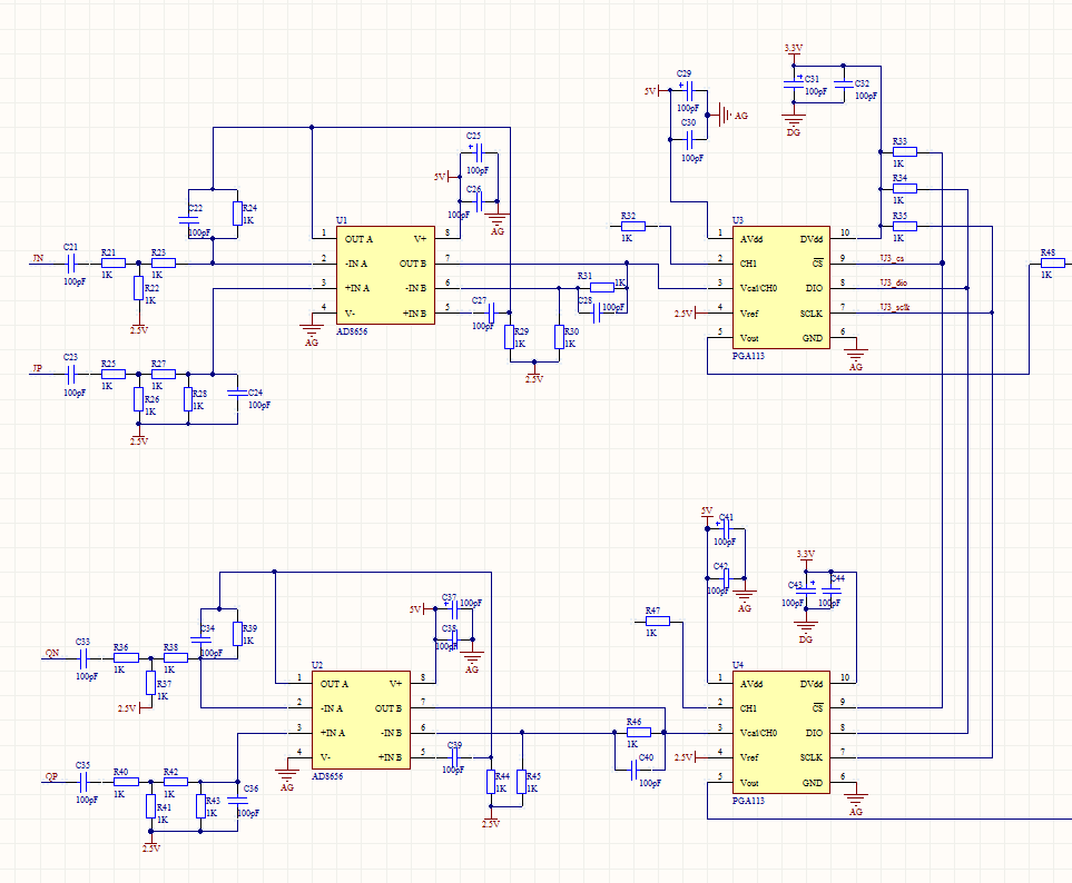
    - On the dual operational amplifier AD8656 circuit, it appears the first stage (amplifier A) is AC coupled  (~1-MHz), therefore the PGA113, depending on gain setting, may not have enough bandwidth for this signal.  On the AD8656 circuit, looking at the second stage (amplifier B), the circuit does not appear to work properly with C39, C27 as shown on the schematic provided above.  Please explain what frequency response and gain is expected at the input and output of the AD8656 circuit? what input amplitude range and frequency range is expected in the application?  Have you verified/tested the AD8656 circuit independently?  

    -The post above mentions that the signal generator is directly connected to CH0 of PGA113.  Are you removing AD8656 from the PCB board during this test?  Please note that the AD8656 amplifier output B is directly connected to PGA114 CH0.

    - Please provide the detailed oscilloscope probe plots, including all three SPI interface signals: CS, DIO, and SCLK on the same oscilloscope capture to verify the timing. Please include a few detailed oscilloscope plots including both a write and complete read sequences so we can verify the timing.  Ensure the plots are labeled with the commands you intend to Read and Write, and ensure the plots display properly.  Kindly attach the oscilloscope probes on a file attachment.

    Thank you and Regards,

    Luis

  • Hi Shike,

    I have not heard from you, if you have further questions, or you have the information/oscilloscope plots described above, please post.

    Thank you and Regards,

    Luis