This thread has been locked.

If you have a related question, please click the "Ask a related question" button in the top right corner. The newly created question will be automatically linked to this question.

4-20mA current loop industrial application

Other Parts Discussed in Thread: INA190, INA240, ADS131A04, THP210, INA149

Hello TI Experts,

I was re-directed from data-converter forum.

I am designing a multi-channel precision data acquisition board for industrial application.
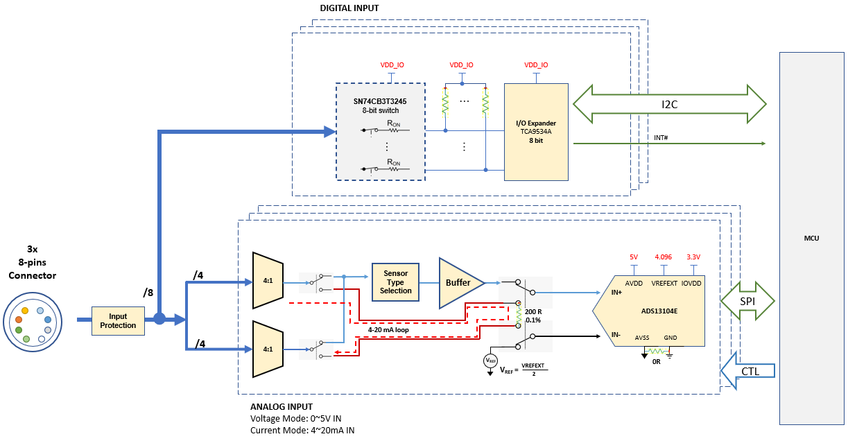
The system is battery powered, so we are dealing with low power design. Figure below illustrates system architecture

Channels are software configured in a group as Voltage or Current inputs. 

  • In Voltage mode, 
    • Analog signals (Single Ended) are mux'ed and buffered before the are sampled by ADS131A04 (pseudo differential)
    • Digital signals are routed to I/O expander via a switch (optional)
  • In Current Mode, 2 channel pins are used for loop +/- 
    • the basic idea is to measure voltage across a precision shunt resistor 


In the application, we don't have control over 4-20mA transducer being connected, i.e. 24V ~ 48V supply and the shunt could be a high side or low side relative to the supply
To avoid ground-loops and maintain isolation, I a differential voltage is measured across the shunt and the concern here is common-mode voltage (Vcm)

#1) Do you see any issue with the above scheme as shown or do I need to shift Vcm with a fully differential amplifier (FDA)?
#2) if we must use FDA, same argument applies and how to protect FDA input against wide Vcm range?
#3) I was looking at the INA190 / INA240, though I am not sure if Vcm is adequate in real application.

I suppose we can use bridge-rectifier to guarantee shunt always appears on low side,
#4) is this sufficient to protect against high Vcm and go directly to ADC differential input?

#5) for protection I may have to split voltage / current paths prior to muxing the channels, is there a TI device that can be used for this purpose or is a SPDT relay the only option? 


Best,
AJ

  • Alex, 

    Because you mentioned the ADS131A04 in this post, I think they pushed this thread back toward me in data converters. It'll have to wait until morning, but I'll try to get someone in the linear group to answer this (and maybe alert some friends in isolation space to this post too).

    Joseph Wu

  • Much appreciated Joseph. Thank you for your help :-)

  • Alex,

    One of my linear apps colleagues, did send me this:

    *****

    I don’t completely follow exactly how the shunt is connected to 48-V high side or low side; and the block diagram does not describe in detail the common-mode conditions.

    An FDA, such as the THP210, powered with a +36-V supply on a G=1 and using 10kOhm input and 10kOhm feedback resistors, could take a 1V across the shunt (or 5V differential signal) up to +48-V common-mode input.  The FDA will see a common-mode around ~26V at its input terminals due to the divider that forms with the input and feedback resistors.  However, I am not certain I understand all the common-mode conditions based on the schematic, he says he has not control over the common-mode; so if there is a case the common-mode is negative, this could put the device outside of common-mode range .  In addition, I am not sure if he is attempting to power the FDA with +5V supply, which will put the THP210 outside the input common-mode range.

    The INA240 shunt amplifier (supported by the sensor group) can support up -4V to +80V  ; but the gain is 20 V/V so this will not work for a signals around 20mA*200Ω= 1V (or 5-V).

    Something like a difference amplifier, INA149 can take up to ±275V common mode and provide a pseudo differential output.

    As you mention, an isolation amplifier could work providing the differential output

    *****

    I'll try to get a response from the isolation amplifier side of things.

    Joseph Wu

  • Hi Joseph,

    Thanks for your help.

    Let me try and clarify with the diagram below 

    For bus-powered sensor, we have the choice of making low-side (A) or high-side (B) current measurements. Though, it's much simpler to connect Rshunt on the low side and reference to system ground, voltage drop across Rshunt can be directly measured by the ADC... For low side, Vcm would not be a concern, i.e. assuming 20mA and 150R shunt, Vcm = (0V + 3V) /2 = 1.5V which is centered at mid-rail assuming VREF = 3V so far so good...

    Assuming high-side, according to INA240 datasheet it's available gain ={20,50,100 and 200 V/V}. Correct me if I'm wrong, Rshunt can be sized for 24mA full scale. Assuming Vout = 3V and G= 50 gives 2.5Ohm. Vout would range from 0.5V (4mA) to 3V (24mA). Vcm would be a concern here but we can determine the worst case, i.e. (48V + 47.5V )/ 2  ~ 48V which is well within INA240 common-mode.

    However, in cases where we have a 3-wire (C) or self-powered sensors (D) connected, there would be a Voffset present so I can not tie my system GND directly to loop return. Also, I am not sure what Vcm is going to be, hence the confusion..

    I need to make a differential measurement and the concern is violating Vcm... Perhaps I am missing something here but I am not sure how the system can support case C and D 


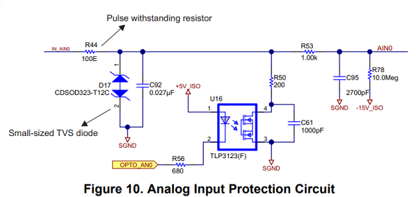
    I was reviewing EVM tidu392 and from the schematic, both current / voltage share the same signal path. In current mode, R50 and optomos take care of IV conversion and the ADC makes direct measurement as per case (A). It's not clear to me how the 4-20mA loop is powered up ... 

    The EVM is powered from +24VDC and it can't be powering up the 4-20mA loop, i.e. SGND is isolated from GND. 

    Best,
    A.J