This thread has been locked.

If you have a related question, please click the "Ask a related question" button in the top right corner. The newly created question will be automatically linked to this question.

Problems with INA229-Q1

Part Number: INA229-Q1
Other Parts Discussed in Thread: INA229

I am having problems configuring the INA229 over the SPI buss. I have tried two different parts and they have the same issues.

I can read the Manufacturer ID,  and Device ID without issue.

When I try to write FFFF to the ADCCONFIG_2 register it will only read back as 3FFF. I cannot get anything higher than 3FFF.

Also when I send a reset command on power up, this register is reading 0000h where the manual says it should default to FFF8.

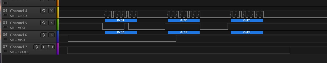
Writing to ADCCONFIG_2 register

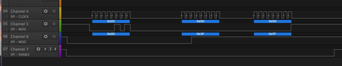
Reading ADCCONFIG_2 register

Thanks

  • Hello Philip,

    Thank you for using the TI forum. I am able to read and write to those registers fine in my setup.  I have a few questions about your setup/firmware to we can get this working for you.

    Can you check the values that you are using for CPOL (polarity) and CPHA (phase) in both the firmware and on the logic analyzer SPI decoding settings? SPI should be in Mode 1, with CPOL = 0, and CPHA = 1.

    Can you tell me what frequency your SPI clock is running at?

    Also, one other thing to look for is the MCU port settings for the SPI pins.  I had one customer tell me they were having a problem when the settings were set to open-drain for the SPI clock because the rising edge of the clock was too slow.

    When I read the default value for ADCCONFIG_2 I get 0xFB68.  I checked with design, and 0xFB68 is correct, so that needs to be updated in the datasheet.

  • Hello,

    I switched my SPI to mode 1 and it's working now. Based on the datasheet I assumed it was mode 0 since  "Mode 0: Clock phase is configured such that data is sampled on the rising edge of the clock pulse and shifted out on the falling edge of the clock pulse." Which seemed to be what the datasheet was saying. You should really put Mode 1 in the SPI section.

    Other issues I've come across:

    The resolution settings on page 9 are incorrect. Full scale shunt voltage readings are 7FFFF0 for both ranges, this is 8388592 decimal.

    163.84 / 8388592 = 19.53 nV/LSB.   I divided the returned value by 51200 to get the correct value in mV

    40.96 / 8388592 = 4.88 nV/LSB.      I divided the returned value by 204800 to get the correct value in mV

    Also. the temperature resolution also seems incorrect. It was about 5C off with that value of 0.0078125.

    I found 0.0065 to be much closer, though this was just for room temperature. I will need to check in a temp chamber.

    I have yet to check the Bus Voltage resolution.

  • Philip,

    I am glad you were able to get it working. Thank you for the feedback on the datasheet. I have forwarded this information on to team that works on the datasheets.