Part Number: LMH5401
Other Parts Discussed in Thread: THS4513, LP2992
Hello amplifier experts,
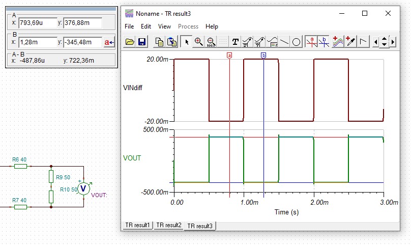
we used the THS4513 op amp in our circuit to amplify a differential signal with approx. 40V/V. By now, we switched to the LMH5401 due to the better GBP and thought it would work the same way (beside the layout changes of course). The LMH5401 was simulated in LTSpice and Tina TI to check if it was capable of delivering a required gain of 40 V/V, cause the THS4313 does so. You can find the simulation results in the following:

As you can see, the LMH5401 fails to deliver the set gain of 40 V/V. The same result was achieved with smaller resistors (10 Ohms and 375+25 Ohms). Where does that come from?
Bigger resistors like Rg=2k and Rf=80k are a hard requierement because the op amp is used in a op amp integrator setting and the capacitor size of 47pF can not be changed.
The layout and schematic was designed almost the same way as in the LMH5401 EVM. We set up dual supply of +2.5V and -2.5V from two LDOs (TPS72325 & LP2992). The output load is 200 Ohms (internal resistors included; with a 50 Ohms terminated oscilloscope). The op amp is used as differential Input / Output.
The problem is, that if we set up a gain of 20 V/V, 40 V/V or even 100 V/V with the respective resistors, the measured gain at the output is way less than expected,as you can see in the table below. A lower gain of 2 V/V, 4 V/V and 10 V/V worked correctly (with a really little gain loss though).
First, we thought that the LMH5401 somehow is not able to achieve higher gains, but as stated in the datasheet Rev. D chapter 6.5 Electrical Characteristics, a gain of 32 V/V was used to test the GBP as well, so do we miss something important?
Our tests circuit uses the HM 8134-3 signal generator for creating a sine wave with 20mVpp. We tried to change the frequenzy from 100Hz to 10kHz but it did not matter at all.

Note: the measured / estimated gain at the osc. is 4 times less than the total gain due to the voltage divider at the output: 200 / 50
Do you have any suggestions? We double-checked almost anything by now. Please help us out!
Best regards,
Michael Bura