This thread has been locked.

If you have a related question, please click the "Ask a related question" button in the top right corner. The newly created question will be automatically linked to this question.

INA230 reverse protection

Part Number: INA230

Although the INA230 does allow for negative differential voltages on its analog inputs, it doesn't allow for negative common mode voltages (something that is pretty commonly seen in the automotive environment).  It is easy enough to protect the 3.3V power bus from these voltages.  But what is the best way to protect the analog inputs?  Could I use a low-side blocking diode - would the floating reference cause issues for the sensor?  What about blocking diodes between the analog sensor inputs and the sense resistor - wouldn't the diode drop across the inputs be more problematic than the floating reference?

Thanks,

-paul

  • Hi Paul,

    I think both will work in certain situations, but with limitation in others. A low side blocking diode shouldn’t affect the sensor itself, but may pose a problem for communication due to different ground levels. Blocking diodes on the input pin may cause too much error, I would avoid this one.

    A Schottky diode plus a resistor (50 to 100 ohm, which is unfortunately larger than the normally recommended 10 Ohm) in front of the each of the input pins should be effective, maybe you could look into it to see if it is acceptable.

    Regards, Guang

  • Hi Paul,

    maybe this post interests you:

    Kai

  • I have already implemented option one (the low-side blocking diode) in design.  I haven't seen any communications issues.  But...what I have seen is that when the analog pins are connected to a load which doesn't go through the low-side blocking diode, there are sometimes significant errors in the shunt measurement of the INA230.  The error isn't uniform from board to board or even across a given board (I have five INA-230s in the design).  But it is consistent and significant (at times as high as several hundred counts).

    Is it possible that the issue is this range of common-mode voltages allowed?

    I think the low-side blocking diode means that the common-mode voltage on the analog pins will be about -0.7V.  Just outside of this -0.3 to 30V specified range.

    What do you think?

    -paul

  • Update: I just tried replacing the low-side blocking diode with a Schottky.  It should cut down that offset down from 0.7V to about 0.5V.  Still outside the allowed -0.3V common-mode range...but...less so.  My error counts decreased by about half.  So...I'm thinking that the low-side blocking diode isn't actually an option.

  • Hi Paul,

    You’re right that 0.5V is still outside the spec, and it will continue to be a problem. Whatever scheme you end up choosing, the input pins must not be 0.3V or lower relative to ground pin.

    If accuracy degradation can’t be tolerated when input common mode dips into the negative region, you may want to consider level shifting INA230. Another option is to choose an analog output current sense amplifier that can tolerate negative common mode voltages. I understand both approaches bring increased complexity.

    Regards, Guang

  • Hi Paul,

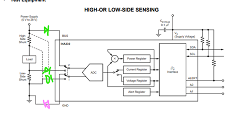
    could you make a sketch how you want to connect the diodes to the INA230?

    Kai

  • The pink would represent the low-side blocking diode.  This one causes common mode range issues when the power supply to the load is floating.  The green represents what I tried since the low side doesn't work.  But...this causes a measured shunt voltage of 0V by the sensor (I don't understand this yet...)

  • Hi Paul,

    Please email or post here if you have further questions.

    Regards, Guang

  • Hi Paul,

    But...this causes a measured shunt voltage of 0V by the sensor (I don't understand this yet...)

    It may have something to do with the green diodes hindering the flow of input bias currents.

    Kai