This thread has been locked.

If you have a related question, please click the "Ask a related question" button in the top right corner. The newly created question will be automatically linked to this question.

INA199: not working as expected.

Part Number: INA199

Hi,

Hope you are doing good

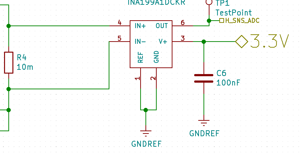
We are using INA199A1 IC to measure the sense current through the sense resistor to measure the current going into or ou tof the battery.we have a 4.5mohm sense resisiotr. and the input to Ina199 Ic is 3.3V

Our application is very similar to Section 9.2.2 figure 29.

instead of having a voltage divider, we have reference voltage from a DC source directly

We chose a reference voltage of 1.5V and when we tried to measure the output when there is no current passing through the sense resistor and we found that we are reading 3.3V out.

We tried connecting a voltage divider for the reference input. At voltage divider we were measuring 1.46V and again tried to check the output voltage and it was reading 3.3V. out.

Shouldn't the output read the reference voltage when there is no current flowing through sense resistor( zero voltage drop across sense resistor).

The input to the voltage divider is 3.3V . we thought if there is a problem in the board,and changed the board and observed the same behavior We even changed IC and checked but the found that the results are same.

What might be be triggering such behavior?

Can you please help us with this?

Thank-you

Warm Regards

Harini Krishna

  • Harini,

    Thanks for using the E2E forums!

    When you say you are attempting to measure the output with no current passing through the resistors, how are you doing this? Are you simply not applying a voltage to the resistor?

    Just to eliminate the obvious, can you probe the input pins to ensure that there is no differential voltage being created across the device?

  • Hi Carolus ,

    thank-you for the reply.

    We are using voltage divider circuit 0.55 V through a resistor divider circuit. We are able to measure 0.55 V reference when there is no differential input connected. The pins are floating. 

    As soon as we connect the differential input and without applying any differential voltage, the reference voltage reads -0.445V. 

    When the  input terminals are connected without applying any differential voltage, the output should read the reference voltage?

    We are measuring a low side signal and we followed the  Section 9.2.2 figure 29. ( sense resistor one terminal connected to battery negative and the other terminal connected to the load/ adapter negative). We are trying to measure charge and discharge current

    what is making the reference voltage go all the way negative as soon as the input IN+ and IN- terminals are connected?

    Thank-you

    Warm Regards

    Harini Krishna

  • Harini,

    How are you connecting to the inputs to apply common mode voltage without differential voltage? Could you show me a schematic of how you are doing this?

  • Hi Andrews,

    The changes on the schematic to the implemented circuit are

    • Ref pin is connected to to a  voltage divider with reference voltage 0.55 V ( it is not connected to ground)

    thr IC is powered through a 3.3V regulator. 

    We kept the pin 4 and 5 floating, as soon as we connect the input pins (4 AND 5) across the sense resistor,  we are observing that the output voltage   drops down to -0.44V without applying any differential signal across the input pins. 

    shouldn't the Output read the reference voltage when  there is no differential voltage applied across the terminals 4 and 5?

    Thank-you

    Warm regards

    Harini Krishna

  • Harini,

    I'm a bit confused here. In your initial post, you say the reference pin is what is being driven to -0.44V, but in this last post, you now say that its the output voltage that is being driven to this state. Between which two pins are you seeing this voltage? Can you provide node voltages for all pins relative to ground to help me understand this?

    Examining this circuit, there is no place in the circuit that exhibits a negative voltage, so something outside the circuit must be driving this condition. You state that the reference divider is being powered by a 3.3V source, but then the divider node is -0.44V. This would indicate that your ground reference at the bottom of the divider must be even more negative than this!

    Looking at your test setup, I don't see how you can bring in the load circuit and not have a differential voltage across the 10m resistor. Are you only applying a common mode to either side of the resistor? If so, what is the value of the common mode being applied? When you "float" the input pins, are you simply breaking the loop where one pin is still connected in the circuit? Also, why are you allowing the inputs to float prior to attaching the load circuit?

    A possible explanation here, without any additional details, is that you are somehow triggering one of the internal protection diodes of the device, which is causing it to latch into this state. If you power up the circuit with the load circuit attached to the inputs, do you still see this issue?