This thread has been locked.

If you have a related question, please click the "Ask a related question" button in the top right corner. The newly created question will be automatically linked to this question.

LM397: Decoupling capacitor

Part Number: LM397

I want to deploy 12 LM397 Voltage comparators onto one PCB board, and TI recommends decoupling capacitor for the power supply. I want to confirm if the capacitors are needed individually for each LM397 or a single capacitor can do the job for the whole board? You can see part of my circuit in the attached picture. I have the comparators set up for hysteresis with a 24Vsupply, a pull up resistor, a resistor network for hysteresis, a capacitor between the inputs to further eliminate oscillations in the transition region, and decoupling capacitors for the power supply noise. The capacitors in question are C1 and C4.

I'm thinking I only need one because having multiple will put the capacitors in parallel and create a larger capacitance than desired, but I am a little unsure  ?
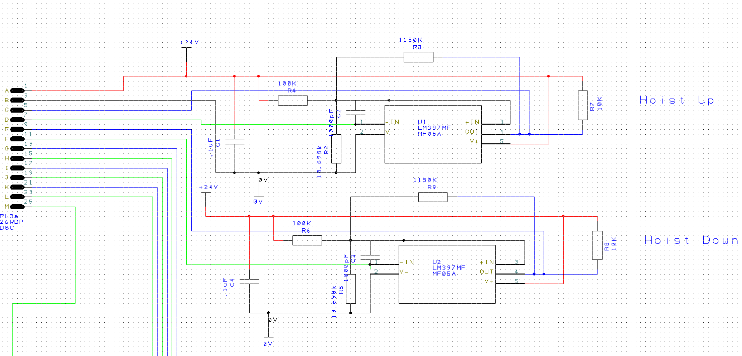
  • Hi Tony,

    Ideally, you should have one 0.1uF cap per device, but two devices can "share" a bypass cap if they are close enough. Because the LM397 is a open-collector output, there will not be the large supply transients on the supply pin, but now the transients are on the "top" of the pull-up resistor. So the "top" of the pull-up resistor should go to the supply pin and it's bypass cap.

    Unless there is an issue with the regulator stability, adding more bypassing capacitance is usually a good thing. The more the better...

    Do not place a capacitor between the inputs. This defeats the action of the Hysteresis by adding a delay and cause "bursts". If you are still seeing "chatter", then increase the hysteresis.

    Also, if there are going to be 12 devices, you may want to increase the value of the pull-up resistor to save some power. Right now the 10k will draw 2.4mA *each* when the output is low. Increasing the resistor value to ~25k will only be 1mA per channel.

  • Thank you Paul!

    This is from the TI layout guidelines for the lm397: "For slow-moving input signals, take care to prevent parasitic feedback. A small capacitor (1000 pF or less) placed between the inputs can help eliminate oscillations in the transition region. This capacitor causes some degradation to propagation delay when the impedance is low. Run the top-side ground plane between the output and inputs." And that is why I put the capacitor between the inputs. How does TI define a "slow-moving signal"?

  • Hello Tony,

    "slow-moving signal" is loosely defined. IT basically means a signal that stays within the threshold long enough to cause multiple transitions. It could be a signal with a risetime slower than the propagation delay, to a true slow-moving signal, such as a battery charge voltage or temperature reading.

    Adding a capacitor to the inputs is not necessarily a bad thing. For the datasheet advice, the capacitor is filtering out high frequency noise that can cause false triggering on the noise when the inputs are close.

    In your case, you added positive feedback (hysteresis). Adding capacitance to the positive input node then suppresses the effect of the hysteresis. You want the positive feedback to "kick" the voltage up/down on the positive input on the first output transition to stop subsequent transitions - and adding a capacitor slows that feedback down - and you can get bursts.

  • Hello,

    I have a follow up to this. How much will changing the pull up resistor value effect the hysteresis voltage setpoints/thresholds? Will I need to change the other resistors if I change the pullup resistor value? If so is there a clean way to do this?

    Thanks,

    Tony

  •  This is my new circuit. If i make the pullup resistor (HUR4) 25k would it be better to reduce the feedback resistor (HUR3) by the same amount that I am increasing the pull up resistor? Or would it be best to make no changes to the value of the feedback resistor and simply change the 10k to 25k?

  • Hi Tony,

    When the output is "high", HUR4 and HUR3 are in series - so HUR3 effectively increases by 10k.

    So, yes, if you increase HUR4, then HUR3 should decrease by the difference.

    If HUR4 increases to 25k, then HUR3 should decrease by 15k to 1135k.

    Also see Inverting comparator with hysteresis circuit cookbook circuit for more info.

  • Thanks Paul,

    The link you posted does not include information for selecting/calculating R3 (the pull-up resistor). Do I just select a value for this (ex 25K) to limit the current. Or does this need to be calculated some other way?

  • Tony

    selecting a value in the 25k range to limit the current is quite reasonable.  Since your pullup voltage is higher than usual (generally see customers level shifting down to 3.3V or 5V), choosing a value such as 25k will improve your VOL level since the sink current is reduced to approximately 1mA.  It really comes down to a tradeoff of speed versus output low logic level.  The smaller the pullup resistor, the faster the output rise time but it comes with the drawback of larger sink current (higher VOL).

    Chuck

  • Chuck,

    Thank you. This will be used for an industrial application where the outputs from the chip will go to an industrial I/O module that takes 24V inputs. This is the reason the pullup voltage is so high.