This thread has been locked.

If you have a related question, please click the "Ask a related question" button in the top right corner. The newly created question will be automatically linked to this question.

TLC084A: Slew Rate and Bandwidth

Part Number: TLC084A
Other Parts Discussed in Thread: TLV9002, TLV9062, TLV9104, TLC084, TINA-TI

Hi,

I would choose a cost-effective and widely used operational amplifier as a current sensor.

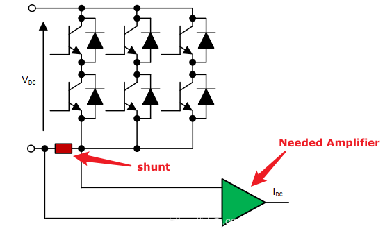
Below picture is my specific application scenario(frequency converter).  please recommend some devices which such same application have used.

Currently, i can not match the parameter 'Slew Rate' and 'Bandwidth' to the actual performance. I do not know, what level should reach on 'SR' and 'GBW'.

  • Hi Holip,

    please post your picture again. It didn't come through. Use the "Insert File" button (paper clip) in the input box.

    Kai

  • Former Member
    0 Former Member

    Hello Holip,

    Thank you for your question.  We would be happy to make a part suggestion.

    Have you given any consideration to the type of frequencies that will be seen or voltage accuracy that will be needed?  If you have any information at all, a more relevant suggestion can be made.  If not, I will give a more generic suggestion.

    Also, as Kai has said, please try to re-post the image of the schematic when you have the opportunity.  I'm looking forward to helping you.

    Regards,

    Daniel

  • Hi Kai,

    Sorry.

  • Former Member
    0 Former Member in reply to Holip

    Hello Holip,

    Without knowing any more details about your circuit or schematic, I'd point you toward this content on high-side current sensing.  It has a few part recommendations at the end.  If you want to use a part for a lower voltage application, I would suggest TLV9002 or TLV9062.

    Regards,

    Daniel

  • Former Member
    0 Former Member in reply to Holip

    Hi Holip,

    Please let me know if the answer provided answers your question.  If I do not hear back from you, I will assume the issue has been resolved.

    You are always welcome to ask a follow up question.

    Regards,

    Daniel

  • hello Daniel,

    Sorry for my late reply.

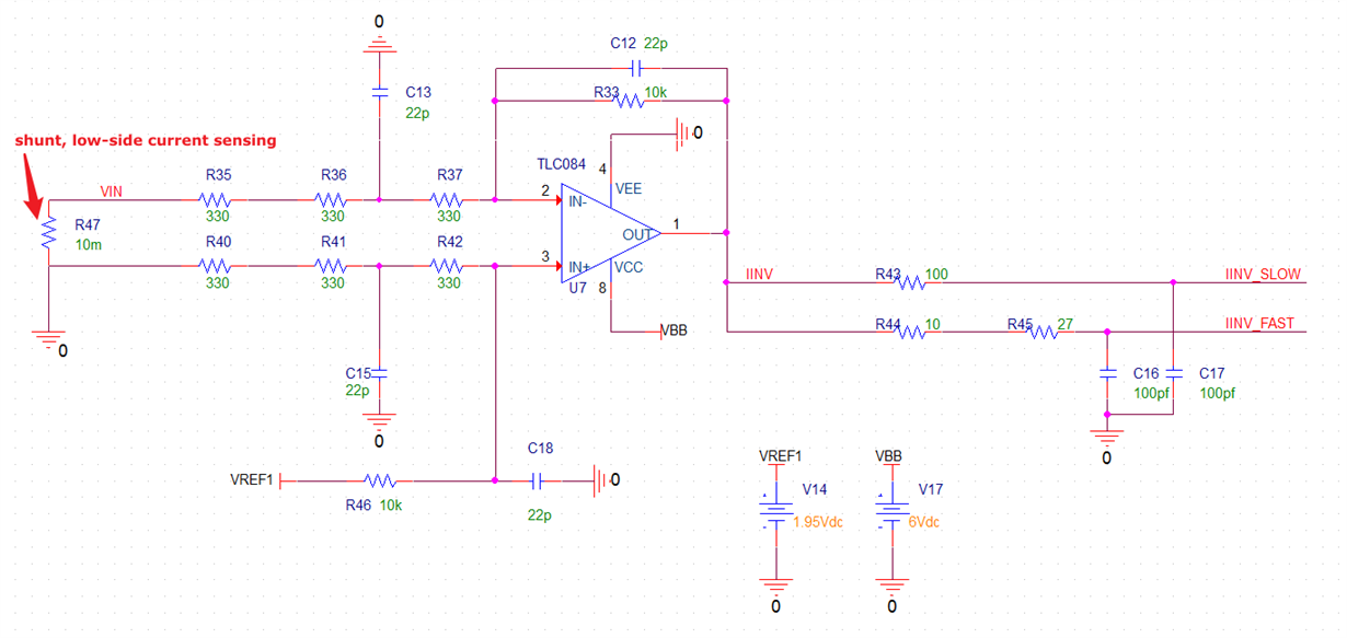
    It's on low-side current sensing.

  • Hi Daniel,

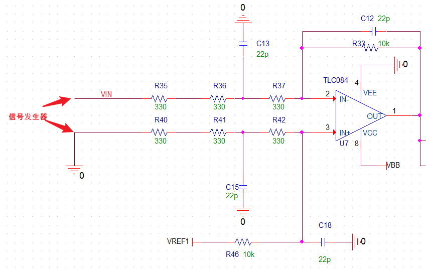
    If I apply function generator which give small sine signal( mv level ) to the actual circuit, just like below. How could I choose generator's load resistance? 50Ohm, or High-z?

  • Former Member
    0 Former Member in reply to Holip

    Hello Holip,

    I would take the fastest frequency of the signal, then multiply by the DC gain of ~30V/V, and then add a factor of 10 to find the GBW that will be needed from an op amp.  This should help you pick a part.

    You will want to set the function generator to the high-z impedance mode.  The 50ohm mode is ideal for when you load the function generator with a 50ohm impedance.  It is always a good idea, in my opinion, to verify the output of your generator with an oscilloscope once the generator is connected to your circuit.

    Regards,

    Daniel

  • Hi Holip,

    why not taking the TLV9104, as already discussed here

    Kai

  • Hello Daniel,

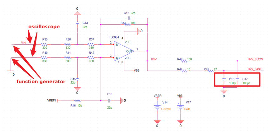
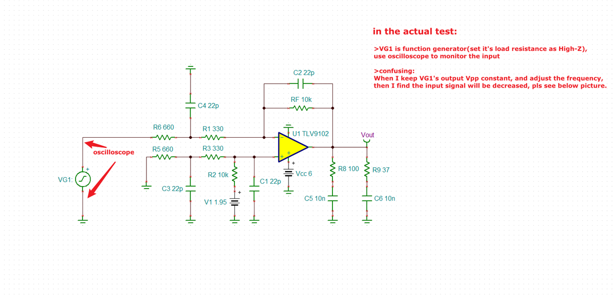
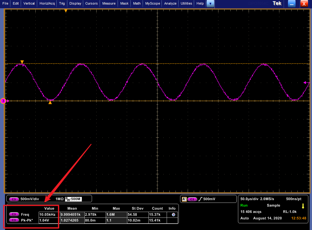
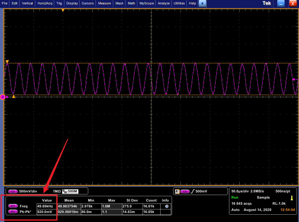
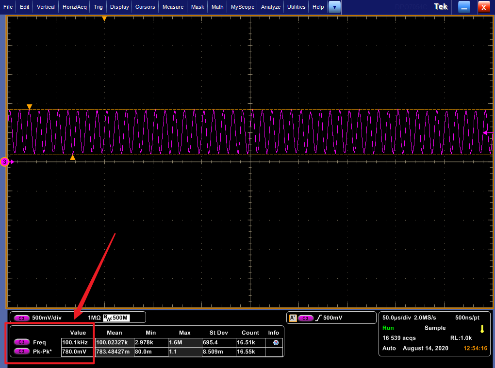
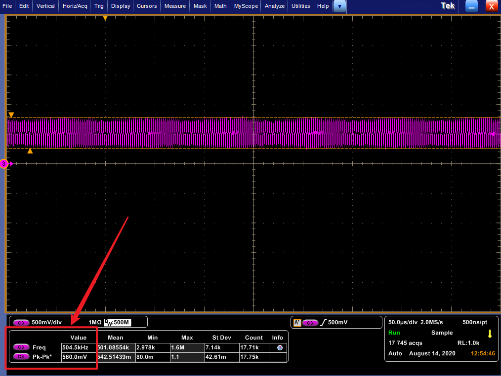
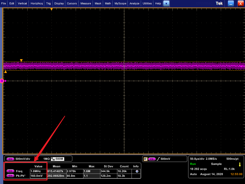
    I set the function generator to high-z mode, generate sine wave and connect to circuit's VIN, and use oscilloscope monitor the input.

    But, when the frequency of sine increases, the voltage of peak-to-peak decreases obviously. What's wrong?

    Best Regards,

    Holip

  • hello Kai,

    TLV9104 has been considered, currently, I used TLC084, but you know, it is so expensive, and I'd like to find a potential one with high performance-to-price ratio to pin-to-pin replace TLC084.

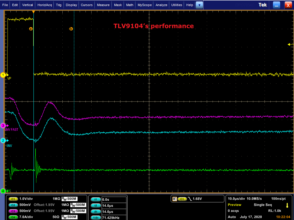
    But in my circuit,  TLV9104 does not perform well on response time and setting time, if you are willing to help me figure out it, then I could attach the test result(wave chart) . Thanks!

    Br,

    Holip

  • Former Member
    0 Former Member in reply to Holip

    Hi Holip,

    What frequency are you operating at?  Would you be comfortable providing images of the oscilloscope screen?

    Regards,

    Daniel

  • Former Member
    0 Former Member in reply to Holip

    Hi Holip,

    What kind of a price range are you looking for in a part?  The 1ku price on ti.com for the TLV9104 looks to be about 1/2 that of the TLC084.

    Regards,

    Daniel

  • Hello Daniel,

    The price of TLV9104 is attractive, if this part can be used in my circuit, fine, good enough on price side.

    Br,

    Holip

  • Hello Kai,

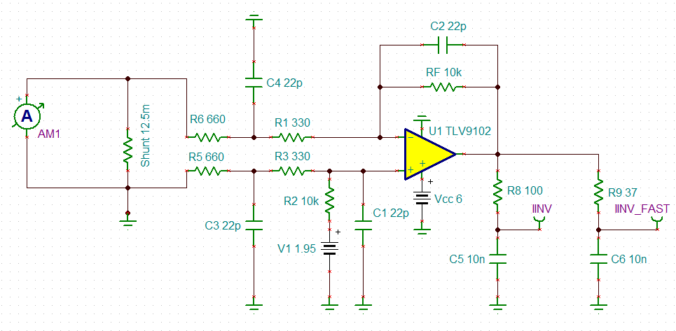
    schematic: pls focus C5/C6 are 10nF.

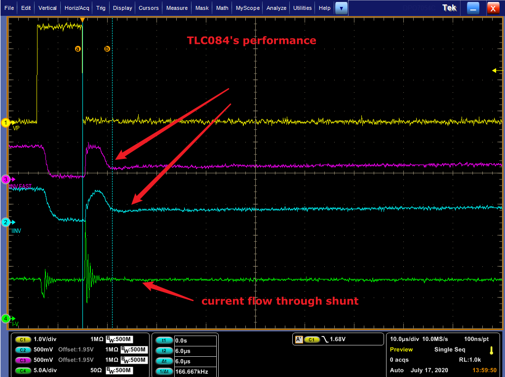
    waveform: seem that tlv9104 can's follow the input well. Currently, i don't  know this caused by slew rate or GBW or capacity of capacitance load(C5 and C6 are too large, if so, where in datatsheet post such performance?)

    Best Regards,

    Holip

  • Hi Holip,

    in your orignial schematic C16 and C17 are only 100pF. In your latest schematic C5 and C6 are 10nF. What is right?

    Kai

  • Former Member
    0 Former Member in reply to Holip

    Hello Holip,

    I have a few suggestions.

    For your issue measuring the output voltage of the oscilloscope, I would recommend you simply take a 10kOhm resistor and drive it with the function generator.  Then, see if the frequency changes with amplitude.  You can then repeat with a 100kOhm resistor.  This is just to entirely isolate the measuring equipment from the circuit and determine whether the loading of the circuit is causing some issue.

    For the waveforms, it is difficult to tell.  But, it might be a slew rate issue.  Do you have any oscilloscope shots zoomed into the "Current flow through shunt" wave?  I would like to measure the change in current across time, but it is difficult to measure the signal in time.  Also, could you clarify which node voltage is "VP?"

    Lastly, if you can attach a copy of your TINA file with the final load capacitance values, I will be happy to take a look at that as well and see if there are any issues with the circuit.

    Regards,

    Daniel

  • Hello Kai,

    Sorry to make misunderstanding, 10nF is the actual valve in my circuit.

    Br,

    Kai

  • Hi Holip,

    as I mentioned many times, the OPAmp becomes instable with such a high capacitive load:

    holip_tlv9102_5.TSC

    Kai

  • Hello Kai,

    I notice this, but, why the TLC084 have such ability? Which parameter should I focus on?

    If possible, my best choice, is to remain current circuit unchanged.

    Br,

    Holip

  • Hello Daniel,

    I did such test, with isolated 10KOhm and 100KOhm, and there is no any decrease for both load, it's could be confirmed that  the decrease causes by circuit itself.

    The total current combines with three phase currents, currently, I don't have such waveform, not have one phase current.

    'VP' is the drive signal for IGBT.

    For the capacitance load, Kai have provided TINA file.

    Br,

    Holip 

  • Former Member
    0 Former Member in reply to Holip

    Hello Holip,

    It is difficult to tell whether a circuit will be stable or not without simulations or a prototype build.  It is generally a good idea to check the phase margin in simulation before building the circuit.

    However, generally speaking a larger capacitive load will cause more issues.  The device has a plot in figure 31 of the data sheet which shows small-signal overshoot versus capacitive load.  Note, that this plot is for a certain test setup with conditions as described in the data sheet.  Since your application will have different conditions, it will probably not match the data sheet exactly.  However, the data sheet will give you some idea of how much load capacitance may work.

    For more information on this subject, I would recommend the TI Precision Labs Series on Stability.

    Regards,

    Daniel

  • Former Member
    0 Former Member in reply to Holip

    Hello Holip,

    In that case, I would just adjust the output of the function generator as necessary and I think you can safely assume that the oscilloscope is reading correctly.  There may be some other setting that is causing this issue, but I cannot tell what it might be.  It might be that the function generator is current limited as you are placing the voltage across a very small resistor.

    Is changing the capacitive load an option for you?  I would try to stabilize the amplifier as a first troubleshooting technique.  Even if this is not the root cause, you will need the amplifier circuit to be stable anyway.

    Regards,

    Daniel

  • Hello Daniel,

    Do you have TLC084's Tina-TI simulation model? I will do a contrast simulation.

    Br,

    Holip

  • Former Member
    0 Former Member in reply to Holip

    Hi Holip,

    Yes, but it will require a few extra steps to put into TINA since the online model is for PSPICE.  Go to the product page for the TLC084 (just click on this link) and scroll down to "Design & development".  Then, click on the tab that says "Design tools & simulation" as shown below.

    Download the PSPICE model folder.  Find the file ending in ".mod" and rename the file so that it ends in ".cir".  Finally, open TINA-TI and follow the steps in this video to import the model.

    Please let me know if you need any further help.

    Regards,

    Daniel

  • Hi Holip,

    your circuit isn't stable. The phase margin is only 30°:

    6471.holip_tlv9102_6.TSC

    Kai

  • Hello Daniel,

    Follow your step, I got the Tina's model of TLC084, thanks.

    Br,

    Holip

  • Hi Holip,

    If possible, my best choice, is to remain current circuit unchanged.

    I'm a bit confused. You have circuit which is instable and does not work properly, but you don't want to change it?

    Kai

  • Hello Kai,

    Current circuit is basing on TLC084, it works well in our products. Considering cost, I want to replace it by another potential one, the best choice is to use pin-to-pin one and do not change the circuit.

    But, if necessary, of course, I will adjust my circuit for the attractive saving by using another op amp. Now, I'm going in this dirction,

    Thanks you!

    Br,

    Holip

  • Hi Holip,

    why must the caps at the output be 10nF? Decreasing these capacitances or increasing the isolation resistors (100R, 37R) would help a lot in increasing the stability.

    Kai

  • Former Member
    0 Former Member in reply to Holip

    Hi Holip,

    Since this thread has not seen activity in some time, I am going to assume the matter has been resolved and will close the thread.  If there are more questions on the topic, please feel free to ask.  You can always start a new, related thread.

    Regards,

    Daniel