This thread has been locked.

If you have a related question, please click the "Ask a related question" button in the top right corner. The newly created question will be automatically linked to this question.

INA233 calibration issue with EVM board GUI

Part Number: INA233

Hello,

I am having trouble in INA233 current calibration with the EVM board/GUI and below is my detail steps:

1.Use the equation in data sheet to calculate the Current_LSB=(Maximum Expected Current)/2^15=15A/2^15=457.7uA/bit,then I choose 1mA/bit as the Current_LSB.

2.Use the equation in data sheet to calculate the MFR_CALIBRATION value=0.00512/(Current_LSB*Rshunt)=0.00512/(1mA/bit*0.5mΩ)=10240(Decimal)/2800(Hex)

3.Power up the INA233 EVM board,start the GUI and write 2800(Hex) into the MFR_CALIBRATION successfully.

4.Connect a 0.5 mΩ external resistor to the IN+/IN- terminal on INA233 EVM board and apply 2A current accross the resistor.

5.Read the VSHUNT_OUT value on EVM GUI and the vlaue is 0.0275V which is correct.

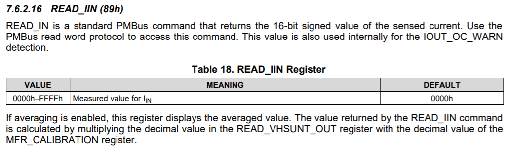
6.Read the READ_INN value and the vlaue is  7FFF/32767 which I suppose is abnormal.

Below is my question:

1.Since I can read the VSHUNT_OUT on GUI directly,is there somewhere on GUI I can read the current directly as well?If not,where can I read the current value and how to translate it into a decimal value in ampere?

  • Hello user3723136,

    I think there is an error in either how the calibration value is being written to the device or an error with how you are measuring the load current to be 2A.

    With Vshunt = 27.5mV, this mean load is 27.5mV/0.5mΩ = 55A, which well exceeds the 15A to 30A max expected current. This in turn would cause overflow in the current measurement register of the INA233.

    Could you read back the calibration register after writing to it to make sure it is working correctly.

    How does this load current return to a ground that is connected to the INA233 ground? Basically, are you sure the ground of INA233 is the same as the ground of the 2A source?

    Also what is the 2A source voltage at? 

    Sincerely,

    Peter

  • Hi Peter,

    Thanks for your reply.You are on the right track.After my further investigation,there is something wrong in my connecting the external resistor to the EVM board.But I have a few more questions as a follow up:

    1.How to set up the INA233 can help to improve current calibration accuray?

    2.Is there a equation that we can use to translate SHUNT_OUT value into  READ_INN value manually?

    3.I have calibrated current with ±3mA accuracy in charging direction successfully and read the current again through INA233 in charging direction,it is still within ±3mA spec. and stable.But when I apply the same current in discharging direction,the value read by INA233 is out of ±3mA spec.(about ±5mA),what should be done to improve this issues so that I can push the current accuracy into ±3mA spec. in both direction?looking forwarding to your reply,thank you.

    Sincerely,

    Sam Feng

  • Hey Sam,

    1. To improve accuracy then in general you need to adhere to the recommendation of the datasheet which are: Kelvin sense connections of the shunt for the input pins, a stable supply voltage that has a properly layed-out decoupling capacitor, and low-impedance return paths to ground for the device GND pin and for the bus voltage source.

    Other ways to improve accuracy are to increase ADC conversion time and/or number of averages for the shunt and/or bus voltage signals.

    The final thing to do is to choose a current_LSB that is as low as possible to maximize mathematical resolution.

    2. If you would rather transfer the Vshunt->load current mathematical processing from the INA233 to the host, then you can certainly do that. There should be two ways. First, you could take the Vshunt and multiply it by the calibration value (see below excerpt from datasheet) or you could convert it to decimal first and then divide by the shunt resistor value. Both are effectively the same thing.

    3. I would refer to my answer for first question. +/-3mA accuracy implies a 3mA*500µΩ = ±1.5µV of input voltage error. What is the load current you are sensing? If you are trying to sense 2A (Vshunt = 1mV), then this equates to 1.5µV/1mV*100 = 0.15% total gain error. This max gain error of the device is specified at 0.1% so you think this is OK, but add in the fact that the input offset (Vos) could be up to ±10µV max, then this means your measurement of 2A could have error beyond your desired ±3mA limit.

    Consider following the example at the end of one of our training videos to calculate total error of a digital power monitor:

    https://training.ti.com/ti-precision-labs-current-sense-amplifiers-gain-error?context=1139747-1139745-1138708-1139852-1140045

    If performing the recommendation in answer 1 does not improve results, then you either have to increase shunt resistor or to perform an offset calibration procedure to remove error from the input offset voltage.

    Sincerely,

    Peter

  • Hi Peter,

    Your suggestions are very informative.I will proceed on your suggestions to see what I can get,thanks for your help.