This thread has been locked.

If you have a related question, please click the "Ask a related question" button in the top right corner. The newly created question will be automatically linked to this question.

LM224A: The simulation does not converge

Part Number: LM224A
Other Parts Discussed in Thread: PSPICE-FOR-TI, LM2902, OPA197, LM224, TINA-TI

Hi Team,

A customer tried to simulate LM224A in PSpice-for-TI but the simulation does not converge.

Here are the details of his inquiries.

"When using the LMx24_LM2902 model all works well when using + and - balance supplies. When I try to use +5 V and GND the simulation does not converge.

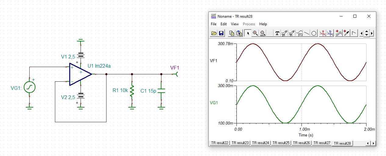
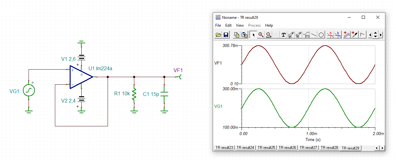
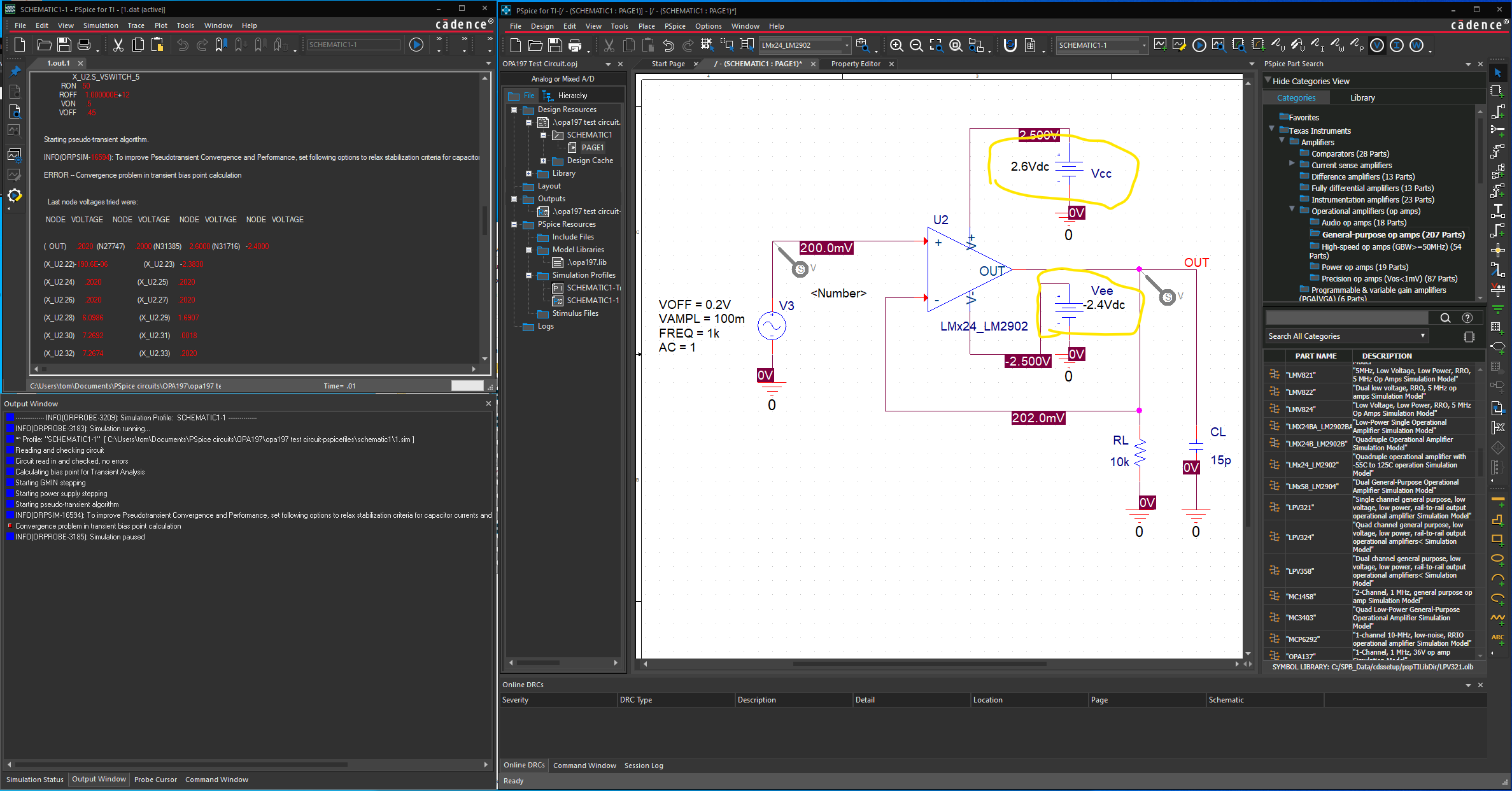
I tried using +2.5V and -2.5V supplies and the simulation runs. When I tried +2.6 and -2.4V supplies the simulation did not run. Am I using the model incorrectly?

When using the LMx24_LM2902 model all works well when using + and - balance supplies. When I try to use +5 V and GND the simulation does not converge.

It was part of the PSpice download.

It was one of many TI opamps modes available."

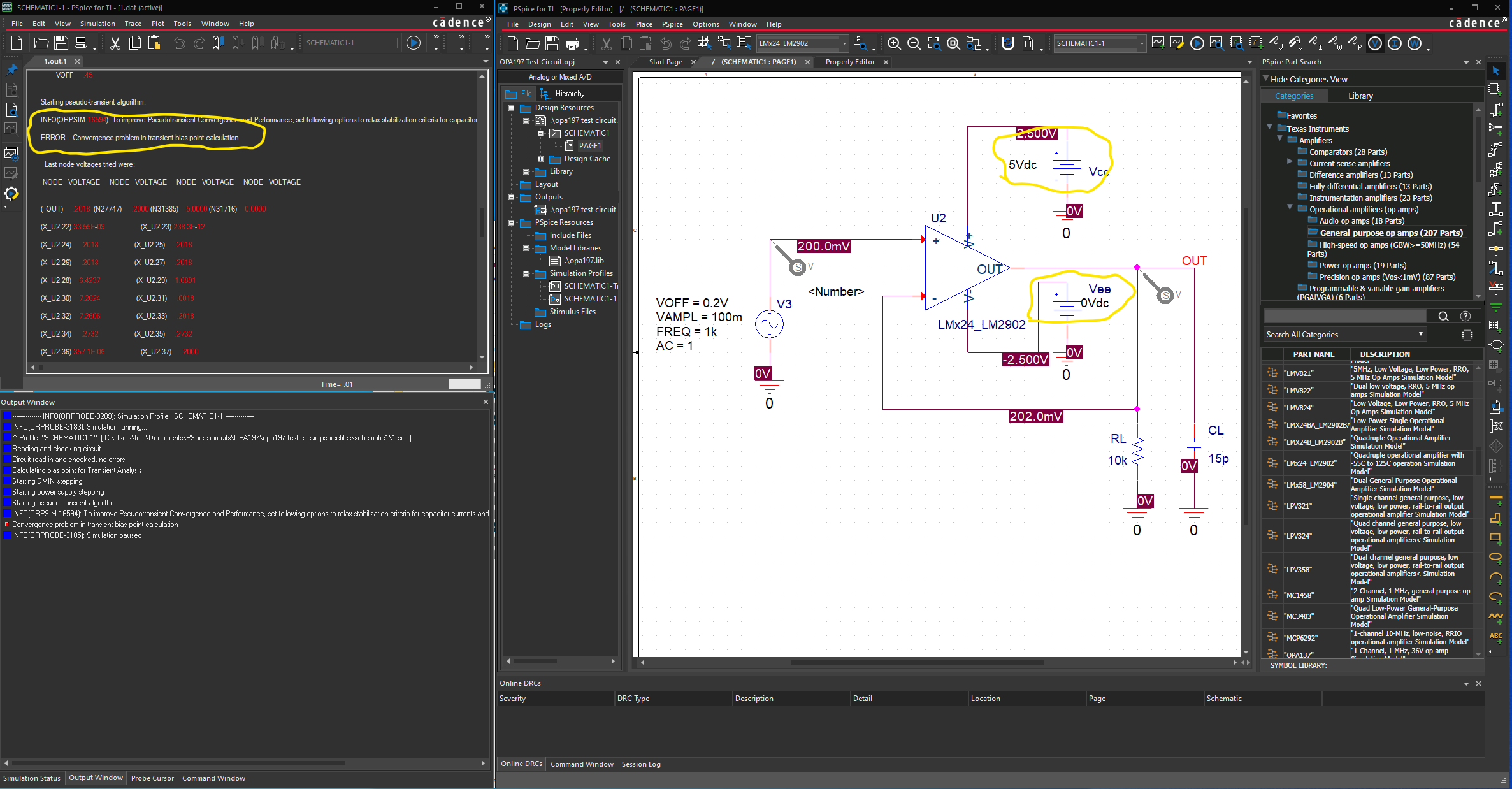
In my latest attempt I made to resolve the problem, I simply took the “opa197 test circuit” adjusted the offset of the signal source to 200mV, and verified the simulation ran properly. I then swapped out the op amp with the LMx24_LM2902 model (under the TI General OpAmp group list) and started trying the different power supply level settings.

Again the simulation ran well and provided the expected results with the supplies set at +2.5V and -2.5V. It did not converge with either voltage supply setting of +2.6V, -2.4V or with +5V, 0V.

The model used was not from the LM224A product page, it was from the library(s) installed with the PSpice-for-TI.

I obtained a couple screen shots showing the model working when the supplies are at +2.5 and -2.5 volts. The simulation failed under my desired +5v and GND condition. It also failed when the supplies were slightly 'unbalanced' at +2.6v and -2.4v.

May I ask your help how to fix this error.

Regards,

Danilo

  • Former Member
    0 Former Member

    Hi Danilo,

    Thank for your question.  I see a transient test in the screenshot that seems to be working.  Is the transient test also the one that does not converge under the different settings?  Was the transient signal centered around 0V when it did not converge?  Also, did the customer get a message about changing the "ABSTOL" and "VNTOL" settings?

    I will try to reproduce the error on my end.

    Regards,

    Daniel

  • Former Member
    0 Former Member in reply to Former Member

    Hi Danilo,

    Were you able to hear back from the customer?

    I've seen this issue with similar circuits.  Do you think the customer would be ok with sending their project so I can mimic the simulation settings and everything else exactly as they have it?

    Regards,

    Daniel

  • Hi Daniel,

    I apologize for late response. I have requested the project files from the customer. I will send to you once I have a copy.

    Thank you for looking into this issue. 

    Regards,

    Danilo

  • Former Member
    0 Former Member in reply to Danilo A.

    Hi Danilo,

    It is not a problem.  Just let me know once you have them in your hand.

    Regards,

    Daniel

  • Hello Danilo & Daniel,

    Attached is the zip file used for the simulations.  I tried to keep it a simple as possible.

    OPA197.zip

    The steps I took to debug are:

    I simply took the OPA197 demo circuit, set the signal offset to 200mV so that the 100mV signal would be positive and verified the OPA197 opamp simulation worked with supplies at +2.5V, -2.5V.

    Swapped out the OPA197 opamp with the LMx24_LM2902 as shown in the screen shot from the TI General-purpose op amps group.  This can be seen in the Sim-okay_+25-25volt.png screenshot.  With the supplies still at +2.5, -2.5 the simulation ran well and produced the output swing expected (100mV swing around 200mV).

    I then simply changed the positive supply from +2.5V to +2.6V and the negative supply from -2.5V to -2.4V and started the simulation.  As can be seen in the Sim-fail_+26-24volt.png screenshot, I received the error message INFO(ORPSIM-16594) suggesting a change in ABSTOL and VNTOL.  I made the changes as suggested but the simulation still failed to converge.

  • Former Member
    0 Former Member in reply to Thomas Borr

    Hi Thomas,

    Thank you for your patience and detailed reply.

    I have reproduced the errors and am working on a fix for the problem.  I will have an update for you tomorrow.

    Regards,

    Daniel

  • Former Member
    0 Former Member in reply to Thomas Borr

    Hi Danilo and Thomas,

    I have made some adjustments to the simulation parameters and model and I would like to deliver these to you directly.  I happen to have Danilo's email address.  So, I will send him my resolution and ask him to forward this to you.

    When you can, please confirm that you have received an email from Danilo so that I know you have received my feedback.  Feel free to post any follow up here as well.

    Regards,

    Daniel

  • Hi Daniel,

    Thank you for working on this and the progress you've made.

    I am definitely willing to try out any possible solution you've developed.  Please be aware that I am relative new to using the PSpice-for-TI program and may need a little hand-holding when it comes to updating the model (assuming it's a model update).  If the solution is by some other method, I'm willing to try that as well.

    Best regards,

    tom.

  • Former Member
    0 Former Member in reply to Thomas Borr

    Hi Tom,

    Sure thing.  I am happy to help.  Please let me know if you do not get an email from Danilo relatively soon.  I can work out a way to contact you directly.

    PSPICE for TI is new for us all and I too am still coming up to speed on it.  To help with this, I've found this series of training videos to be quite helpful.  They're relatively short and to the point.  Video 2.6 covers importing external models.  So, you should be able to follow those steps.  Let me know if you have any issues.

    Lastly, if you have difficulties working certain things in PSPICE for TI, you can always try running your sims in TINA-TI instead.

    Regards,

    Daniel

  • Hi Daniel,

    I received the model file (thank you very much).  I created a directory within the path used for the other model files.

    'C:\SPB_Data\cdssetup\pspTILibDir\mods\LMx24_2902_mod.lib'

    [ I did not place it directly in the standard directory because the model files are frequently updated (overwritten) and did not want to risk losing the modified file.]

    I edited the simulation parameters with "Analysis:Analysis Type: = Time Domain (Transient), Options:=General Settings"

    and with "Configuration Files:Category=Library:Filename=C:\SPB_Data\cdssetup\pspTILibDir\mods\LMx24_2902_mod.lib"

    and with "Options:Analog Simulation:General VNTOL=100.0u, ABSTOL=10.0u, ITL2=200"

    I set the supplies in the test case circuit to +5.0V, -0.0V and the input at 100mV swing offset of 200mV.   When I ran the simulation I received and error message:   

    "INFO(ORCAP-15099): Detected an imported model containing transistors or diodes. For such models, PSpice for TI supports a minimum of one and maximum of three markers. Modify marker settings or use a behavioral model or a model from the pre-installed libraries."       

    I selected OK in the dialog box(es) and the simulation completed with the expected results (100mV swing around 200mV).    I tried with and offset at 300mV and this also worked. 

    But when I set the offset to 400mV, the simulation failed to converge and i received the error message INFO(ORPSIM-16594) similar to the original error message suggesting a change to the PTRANABSTOL=1e-5,PTRANVNTOL=1e-4..

    So the model works much better but it is not completely functional yet.  I'm assuming the LM224 input offset can be up to +2V, correct?

    Since the +5V/GND supply setting was working, albeit with a limited input voltage range, I thought I'd try the new model in my actual circuit.  In this case when I got the error INFO(ORCAP-15099) regarding the model markers, I could not get past that error - even after I selected the "Remove All" markers and tried again.

    Thank you for the progress so far on resolving this issue.  Please let me know if there are any other test cases that would help to fully resolve this problem.

    Best regards, tom.

  • Former Member
    0 Former Member in reply to Thomas Borr

    Hi Tom,

    Well...it looks like the issue is not really resolved after all.  The model should be able to take a common-mode voltage of up to 2V below the V+ rail.  In this case, that would mean the source voltage offset voltage can go up to 2.9V.  And really, it should continue to operate up till it gets close to the V+ rail, just not necessarily meeting the data sheet specifications at that point.  So, clearly something is amiss.

    When you put the new model into your circuit, did you have a marker in place when you tried to run the sim?  I know it sounds strange, but the error message can be misleading when you have 0 markers placed.  I'm assuming you correctly added the .OLB file for the new model into your simulation settings.

    I spent some time today going through this issue and attempting to get it resolved, but have had no luck.  I think the problem is that the model was originally created and fine-tuned in a different spice software with different convergence requirements.  Now in PSPICE for TI, previously unnoticed convergence discrepancies are showing up.

    I'm not sure that just changing the simulation settings is sufficient anymore.  You can try that yourself, but I'm working on a deep dive into the model structure to see if I can determine which part of the model might need to be adjusted.  Unfortunately, this is a time consuming process and I don't have a time frame for how soon it will be done.

    Would you be open to working in the TINA-TI spice software?  I think you would have fewer convergence issues there and it is my understanding that you can import other spice models into the software.

    Regards,

    Daniel

  • Hi Thomas,

    the model works in TINA-TI:

    borr_lm224.TSC

    Kai

  • Hi Daniel,

    For my immediate need I believe I can redraw my actual circuit  (or at least a subset of the circuit) in TINA-TI to verify the portion around the LM224 op amp.  I would prefer the PSpice-for-TI for long-term use.  Do you know if the models will be reviewed for that platform?  I'm not asking for any completion dates - just if reviewing the models in PSpice-for-TI is on any roadmap for future use.  If so, is there any way for me to be notified if updates occur, or would it be easiest for me to just periodically check by running the test circuit in PSpice-for-TI?

    Best regards,

    tom.

    PS.   One more item regarding the LM224 model in TINA-TI, do you know if it includes the 'time delay when the op amp switches between source current and sink current drivers' as described in the TI Application Report SLOA277-January 2019 section 4.4 (case B)?


  • Former Member
    0 Former Member in reply to Thomas Borr

    Hi Tom,

    That is totally understandable.  I am actively working on debugging the issue, though with a different model.  I am hopeful, and also somewhat confident, that once the discrepancy is determined for one model the remaining ones can also be fixed.  But, I do not have any sort of time frame for this because I just don't know how long it will take to uncover it and the process in this case is rather time-consuming.

    As for updates, if you use the library that comes with the parts I would think it should automatically update.  If you really want to be sure, you can check back in every once in while by asking us on e2e.

    Regarding your last question, I would say probably not.  This may be a nuance that is not captured in the model as these older, standard parts seem to have more of those.  I will ask the author of the document himself to be sure.

    Regards,

    Daniel

  • Former Member
    0 Former Member in reply to Former Member

    Hi Tom,

    I asked the author of the article about the model implementing this detail and here is what he had to say:

    "The model on the web does have it implemented in two operating points where only one was request."  He then claims this model runs more slowly.

    "The model in Tina does not have that implemented or a few other missing things. This model is super-fast."

    I've simulated with the model that is available online and I don't remember it being problematic.  But, finicky and slow might just mean it take 50ms to converge rather than 20ms.  I would just pull the online model and work with that since it will have a more complete   Let me know if you have any issues.

    Regards,

    Daniel

  • Former Member
    0 Former Member in reply to Thomas Borr

    Hi Tom,

    Since this thread has gone quiet, I am going to mark it as resolved.  If you need any further help or have any follow up questions, please feel free to comment again or create a new thread.  I am still working on the model debug.

    Regards,

    Daniel