This thread has been locked.

If you have a related question, please click the "Ask a related question" button in the top right corner. The newly created question will be automatically linked to this question.

TL3016: Input noise in this and similar analog comparators

Part Number: TL3016
Other Parts Discussed in Thread: TL081, NE5534A, TL3116, LM360, LM361

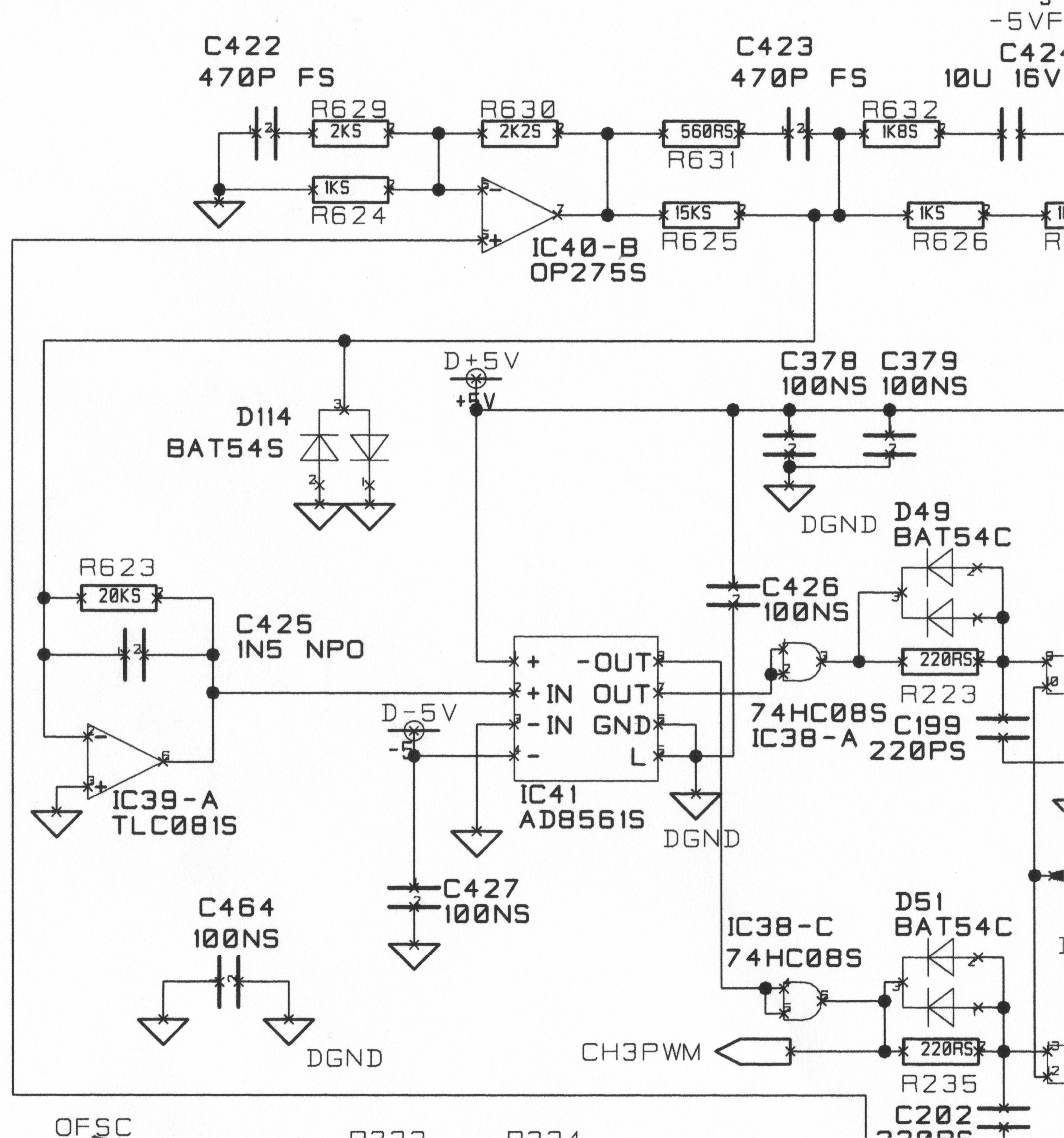
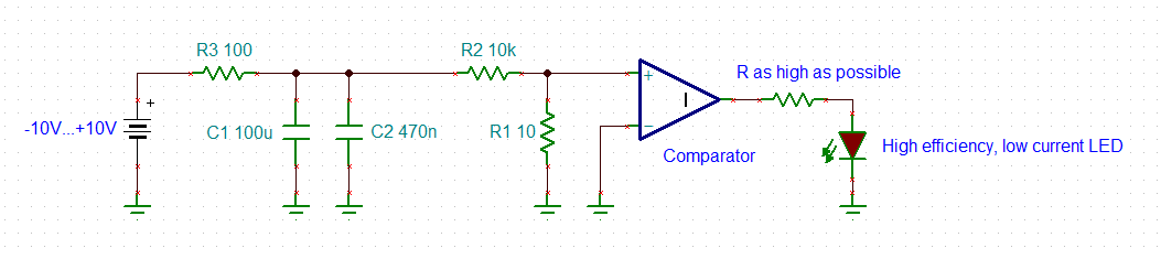
I'm working with a mature high power Class D amplifier design, and am having some issues with noise generated in the naturally-sampled PWM modulator. This comprises a simple analog ramp generator (an op-amp based integrator, creating a roughly 150kHz triangle wave) and, at present, an AD8561 comparator from Analog Devices.  The noise present within the input stage of the comparator appears at the output PWM as a random jitter of the edges -- effectively the comparator input voltage noise is added to the desired signal, and modulated along with it.  Given the amplifier's relatively high power (main rails of +/- 150V DC) the output stages effectively apply 30dB of gain to whatever input noise exists within the comparator -- but nobody seems to be able to comment on how big this is, and which comparators might be chosen as alternatives to help reduce the issue.

The problem is NOT to be confused with the multiple output transitions that can be caused by inadvertent feedback around the comparator.  These aren't a problem (the comparator actually switches very cleanly, thanks to careful attention being paid to decoupling, PCB layout and the fact that both inputs being driven by very low impedance nodes).  Adding hysteresis does NOT help with my specific issue; DC coupled hysteresis simply displaces slightly the threshold at which the comparator switches, and then speeds the transition once it's begun. Adding AC hysteresis (that is, a small positive feedback capacitor) only helps to speed a transition once it's begun.

The noise voltage - which IS the problem -  also shifts the comparator's switching threshold, but does so randomly and regardless of whether any hysteresis is added.  Measurements confirm the total lack of improvement by adding hysteresis.

Can anyone help shed light, please, on the sort of input noise voltage density we may expect from an analog comparator of the TL3016 (which is TI's version of the LT1016m itself something of an industry standard and the predecessor to ADI's AD8561) ?   Is there a general trade between comparator speed and input noise voltage?  Any recommendations for a lower noise alternative?

Thanks in advance!   - Mike Turner

  • Hi Michael,

    don't overlook power supply noise and ground noise. Also, your sawtooth isn't noise-free either.

    Kai

  • Thanks Kai.  I did actually check these points fairly carefully. I've measured the phase noise of the clock that's used to derive the ramp (resulting PWM jitter is well below the noise floor) and also the level of audio-band noise present in the triangle wave -- again very low indeed. I'm targeting input noise of the comparator as I believe the evidence clearly points to this, but thanks for the reminders and for sure I'll still keep an open mind!  In fact I'm going to re-measure...

  • Kai makes a valid point but we will see if we can find any noise density information regarding the comparator.

    However, due to the age of the device, this information may not be available.  One of us will get back to you.

    Chuck

  • Hi Michael,

    can you show the schematic of the comparator's section? Just to see how you drive the inputs of comparator and what is connected to the output :-)

    Kai

  • Hi again Kai

    The comparator inputs are at low mpedance; the non-inverting input is driven by an op-amp, actually an NE5534A, and NOT a TL081 as shown.  Under quiescent conditions the signal here is a +/- 2V peak triangle.The inverting comparator input goes straight to ground. The +5V and -5V supplies are clean and quiet;  and I should re-iterate there's no problem with multiple transitions at the comparator outputs.  The outputs each feed 74HC08 gates which act as buffers and which then drive simple monostables to add dead-time.  The latter aren't the best practice IMHO - but the're really not part of the present concern. (I'd prefer at least proper Schmitt trigger input gates after the monostable RC time constants, to help avoid introducing timing jitter here - maybe even proper dedicated monostable IC's). 

  • Hi Michael,

    to get a feel for the input referred noise of comparator, I would build the following test circuit:

    +/-10V comes from a low noise voltage supply. Low pass filter R3, C1 and C2 provides additional noise filtering. R2 and R1 form a 1000:1 voltage divider. Of course, you can adjust the division ratio to your needs. R1 presents a low ohmic source resistance to the comparator input as in your original circuit. By this the input noise current plays a similar marginal role as in your original circuit. Now carefully and slowly decrease the input voltage from +10V to -10V and check the output of comparator for togglings.

    The circuit should be very well shielded. The comparator should be supplied by batteries (other than the +/-10V input voltage!) and the supply rails of comparator should be low pass filtered by a suited RC network. Have the batteries within the shield as well. Eventually an additional 100n cap across R1 might improve the results.

    Don't connect a scope, voltmeter or else to the output of comparator, as this can introduce additional noise to the input or signal ground. To check for togglings I would connect a LED needing ultra low current to the output of comparator. 

    Kai

  • Hi Michael again,

    I would treat the comparator as an analog circuit,  an analog circuit which is very sensitive and providing a very high gain. So I would connect its signal ground to the analog ground, not the digital ground. And I would avoid powering the comparator by the digital supply voltages. At least add RC filters or RLC filters to the supply voltage pins of comparator and 74HC08.

    Eventually, revise the signal ground routing so that no digital supply or ground currents are flowing through the comparator section. Individual RC or RLC supply voltage filtering can help a lot in this attempt. The 74HC08 circuitry which is producing lots of supply and ground noise should be isolated from the analog and comparator circuitry. Use a solid ground plane and separate the digital and anlog circuitry (including the comparator) from each other. Insert isolation resistors between the outputs of comparator and the inputs of 74HC08.

    Kai 

  • Hello Joseph,

    We were not able to find any "noise" measurements for the TL3016.

    For comparators, Jitter is the effect of internal noise modulating the threshold (as Kai eludes to).  It is *VERY* difficult to measure "noise" like an op-amp.

    You are probably used to using audio op-amps that have low (<1Hz) noise corner frequencies. High-speed comparators use high-speed (several GHz) semiconductor processes – which tend to have high noise corner frequencies (10kHz to 1MHz). This means more noise in the lower frequency "audio" region.

    The problem is that you are essentially up-converting audio frequencies to higher frequencies, where the noise is higher, then converting back down to audio.

    Other than finding a "low jitter" comparator – I don’t think there is much that can be done externally to minimize the internal comparator noise.

    You need to compare (Ha!) the different devices and see which is the best for noise in your application. I don’t think there is one spec you can look at to say it is “the best”.

    Please also have a look at this application note

     Measuring Output Jitter

    As you can see, they are using $20k worth of equipment to do the measurement...not easy...

  • Hi Paul

    Many thanks for the feedback (no pun intended on my part, either! :-) which very much confirms what I'd suspected;  that is, (a) this is a difficult parameter to measure, and (b) that very fast comparators by their nature are probably going to be rather noisier than I'd like at audio.  I've got some TL3016's on order anyhow, and also the slightly slower TL3116 which is an easy thing to try as it's pin-for-pin.  The LM360 looks interesting, too, 20nsec so rather slower (but fast enough I think) and allows for slightly higher rail voltages. These are attractive as a higher ramp voltage allows me to reduce the conversion gain of the modulator (and replace it with "quiet" gain earlier in the signal chain.

    I've also made some improvements to the circuit by the simple expedient of replacing the TL081 integrator in the modulator with a TI 5534A, and also drastically reducing the value of the clock coupling capacitorfeeding that integrator, from 10uF in my client's original design to 4.7nF, which is still low enough impedance to satisfactorily couple the clock whilst at the same time greatly reducing the audio-band noise gain in the integrator stage. This improvement made a worthwhile but still only small (2-3dB) measured difference in the noise floor in the recovered analogue signal at the comparator outputs, when measuring the signl-level circuitry only;  but strangely in the powered amplifier the difference is more like 10dB; at the moment I've no idea why!  But I wonder if it may be due to a substantially lower impedance at the 5534A's output, relative to the old and rather inferior TL081. 

    The comparator noise floor is still significant though, so I'm looking forward to trying out some emprical substitutions as you suggest.

    Many thanks for your efforts to locate the noise data (interesting that it's so little quoted) and for the constructive and helpful comments.  Likewise Kai, thanks for your input.

    Best regards

    Mike  (not sure where "Joseph" crept into the discussion, but no matter!)

  • I should add, I've just tried the MAX913 - this was not dramatically different but measurably quiter (2-3dB) so a worthwhile improvement nonetheless.  Looking forward to trying some others. The LM361 looks especially interesting, as it allows for 15V supplies - hence a much bigger ramp voltage and much reduced conversion gain (hence input noise is proportionately less of an issue, even before any improvement there might be from this slower-speed device.

    Thanks again to both you and Kai.

  • Hi Michael,

    the "Joseph" came from me. It's someone from a neighbour thread. I apologize for this.

    Good luck with your project :-)

    Kai

  • closing the thread because it appears there are no further questions

    if any further support is needed, feel free to reply or open a new thread.