This thread has been locked.

If you have a related question, please click the "Ask a related question" button in the top right corner. The newly created question will be automatically linked to this question.

WEBENCH® Tools/INA181: INA181 referance design verification

Part Number: INA181
Other Parts Discussed in Thread: INA260, ISO7842, TIDA-01590

Tool/software: WEBENCH® Design Tools


HI All,

I want to measure 1500C DC 30A
So i am planning to use INA181A3
I am going to use BSV001 (1millohm) shunt resistor and i am  power up my INA181A3 with seperate DC 5v power supply.

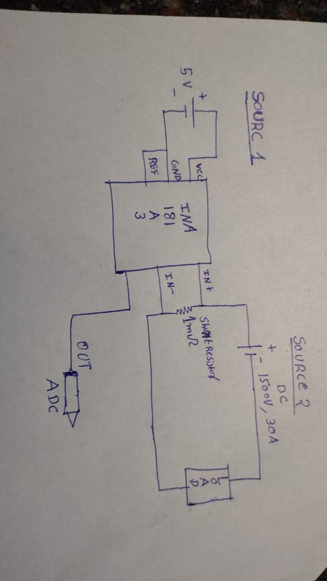
i have attached below setup.

since my max voltage accross the shunt resistor is going to br 0.030mv shall i go with this design ?



  • Santhosh,

    Unfortunately this design will not work as is, due to a violation of the common mode of the device.

    Our current shunt monitors differ from traditional difference amps and operational amps in the fact that they can measure a voltage at the inputs higher than the supply of the device. That said, even this ability has limitations, which are shown in the datasheet of the device. For the INA181, the maximum allowable common mode voltage is 26V, while this design is a high side application, and the inputs are exposed to 1500Vdc.

    There are a few ways to alter the system so that you can do this. The first is to implement a low-side measurement, which will remove the common mode issue, but this comes at the expense of certain trade-offs, the largest of which is losing the ability to detect faults to ground due to the load now having the shunt resistor in line with the ground node. We have a TI Precision Lab that discusses the pros and cons of these implementations here, and how to set them up properly. 

    If you decide that you still wish to implement on the high side, you need to implement a method to reduce the common mode of at the inputs of the device to an acceptable level. If power dissipation is not a concern in your application, one way to do this is to clamp the device with a zener diode to ensure the device remains within common mode range, and dissipate the remainder with a power resistor. We have provided a 400V design in this reference.

    Let me know if you have any additional questions!

  • Hi, Thank you for the qucick replay.

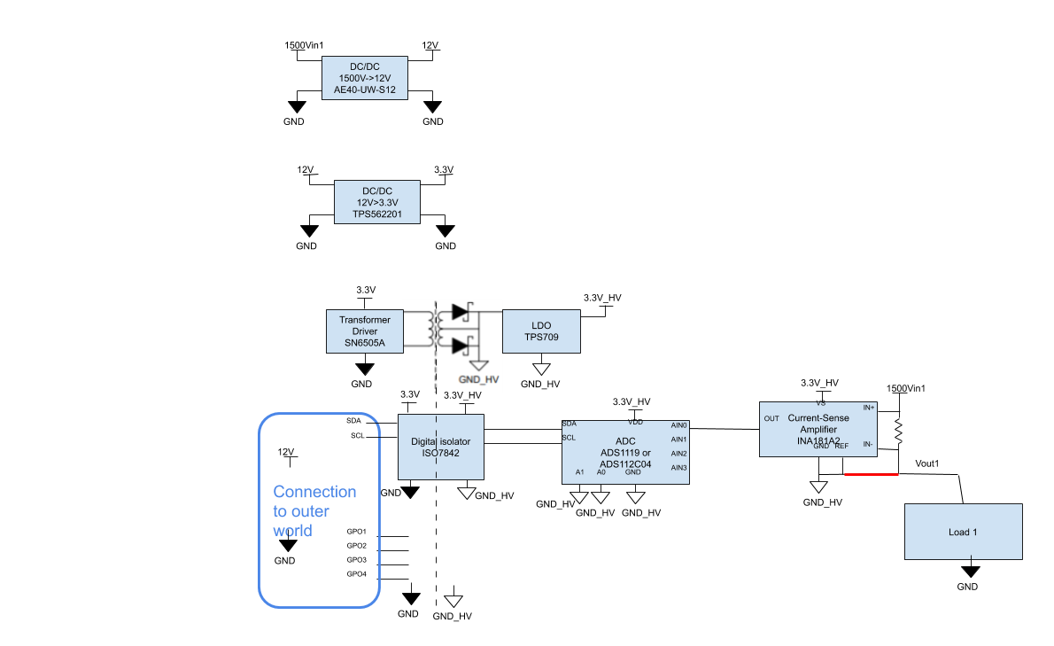
    Actully in my design i am going to isolate compleately my hight voltage and low voltage sources.

    I have reffered this design

    The  above design  uses INA260 and it has lot other features includeing voltage and power measumet etc.

    But what i want is only current measurment, so i am thinking of using INA181A3 insted of INA260 by following same way of isolated desing used in INA260 desing (link attached above)

  • Santhosh,

    This makes more sense. With isolation and a floating ground to ensure the common mode remains within defined spec, this should work. 

    Regarding using the INA181, you should be able to do this. The INA181, ADC, and their respective power supplies will need to share a common ground on the isolated side to ensure safe operation. Also, you will need some way to pass the data from the ADC back to whatever logic you are using if that logic is located on the primary side, similar to how the ISO7842 was used in the attached reference design. 

  • Thank you Carolus,

    I have one question related to this way of isolated design.

    Connection betwen the "IN-" pin and "GND" pin is necessary or not?

  • Hello Carolus,

    I work with Santhosh on the same project, and I just what to clarify our question.

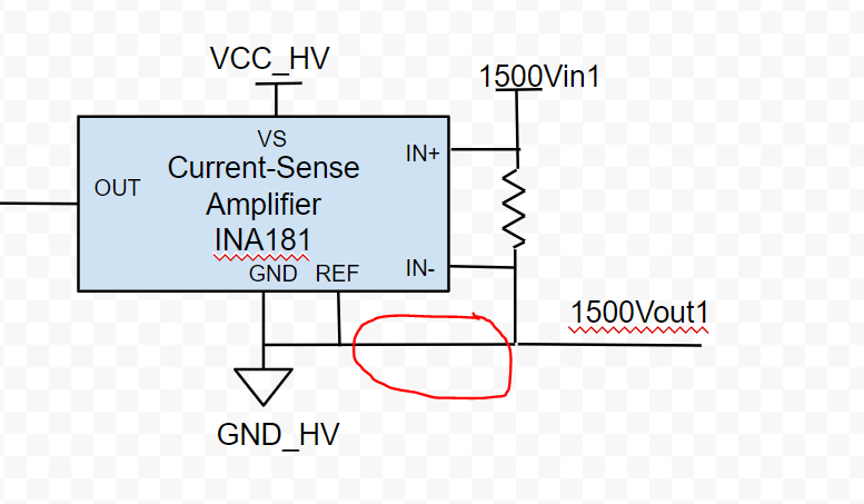
    Attached is basic block diagram of circuit which we are making for measuring 1500V DC up to 30A.

    We are just not sure do we need this connection marked in red?

    In 1200V reference design from TI https://www.ti.com/lit/ug/tidudm5/tidudm5.pdf?ts=1596144656148&ref_url=https%253A%252F%252Fwww.ti.com%252Ftool%252FTIDA-01590

    there is 0 ohm resistor and we are not sure is it placed or not in final design

    Regards,

    Dragan

  • Santhoth and Dragan,

    Yes, this connection is needed. They way these reference designs are configured is that "GND_HV" is a floating ground stacked on top of the 1500V load. As I mentioned in my initial post, the common mode voltage that can be handled by the INA181 is from -0.2V to 26V. However, this voltage at each pin is with respect to the ground pin of the current sense amplifier. By having this connection, you are effectively forcing the common mode of the device to 0 to ensure it operates within specified range. As you can see, the load line is terminated at proper GND, and without this connection to the HV ground defining the stackup, the common mode seen at the pins would be 1500V as I said in my first response.

    Also, something I caught during my analysis: there is a poorly drawn reference for the transformer taps leading to the LDO:


    Make sure that the taps of your transformer are configured correctly to the LDO IN and GND as per the actual schematic:

  • Hi Carolus,

    Thank you for your answer and clarification! For me everything is clear, why we should connect it.

    Yes, this is basic block diagram, when we draw schematics we will pay attention about exact connections.

    We are now searching for transformer which can withstand 1500VDC. Current transformer 750315240 by Wurth in reference design 

    https://www.ti.com/lit/ug/tidudm5/tidudm5.pdf?ts=1598647634353&ref_url=https%253A%252F%252Fwww.ti.com%252Ftool%252FTIDA-01590

    is for 1200V, as we understand Reference design "The transformer used in this application is the Würth 750316031 (1:1.75 → 3.3:5.775). The transformer package is selected to have a working isolating voltage of > 1.2 kV and creepage and clearance ratings of > 11 mm. The only limiting factor for performing a 1.5- kV current sensing using this same design is the clearance of the transformer."

    Regards,

    Dragan

  • Dragan,

    As the reference design documentation specifies, at this voltage level, increased creepage and clearance are needed to meet certain safety standards as the voltage grows larger. We put a slot in the board to meet the creepage spec, but the clearance was limited by the transformer.

    A reason for this choice is that the push-pull transformer used in this design is a catalog part that is designed to be used with the SN6505. That said, the clearance between the primary and secondary was not wide enough to achieve 1500V, so we settled for a 1200V design. At the time this design was published, a custom transformer would have been necessary to get to 1.5kV, but that was quite some time ago, and there may be additional catalog parts now that would satisfy these requirements.  

    I would recommend first specifying your specific isolation requirements with your team. Then you can determine what transformer is needed for the isolated bias supply. There shouldn't be a need to change the SN6505 in the above reference.

  • Hello Carolus,

    Thank you for answer.

    We sent inquiry to Wurth regarding transformer. As we searched their website and portfolio

    https://www.we-online.com/web/en/electronic_components/produkte_pb/products_pbcm/product_spotlight/ti_sn6505b.php

    there is no off-the-shelf transformer which can be used with SN6505 and which has increased creepage distance. The similar is with Bourns

    https://www.bourns.com/docs/product-datasheets/hct.pdf

    We are not planning to change SN6505, but in case we can't find appropriate transformer, we will maybe need to implement driver for transformer from some other manufacturer.

    Regards,

    Dragan

  • Hello Carolus,

    Can someone from TI, which worked on this reference design TIDA-01590, confirm us what should be creepage/clearance distance for transformer to satisfy 1500 V DC?

    Used transformer 750316031 has 11mm min creepage and clearance distance and I am thinking it is enough for 1500 V DC operation.

    Regards,

    Dragan

  • Dragan,

    This is a tough question because it doesn't have an objective answer. This is because the answer has everything to do with the standards and specifications you are trying to meet. This may offer some additional clarity. 

    The parts for TIDA-01590 were chosen for this design to meet the following standards:

    – 8000-VPK reinforced isolation per DIN V VDE V 0884-10 (VDE V 0884-10):2006-12

    – 5.7-kVRMS isolation for 1 minute per UL 1577

    – CSA Component Acceptance Notice 5A, IE 60950-1 and IEC 60601-1 End Equipment Standards

    – CQC certification per GB4943.1-2011

    – TUV certification per EN 61010-1 and EN 60950-1

    – All DW package certifications complete; DWW package certifications complete per UL, VDE, TUV and planned for CSA and CQC

    It may be that if you do not need to meet all the above standards, 750316031 may indeed work for your design for 1500V.