This thread has been locked.

If you have a related question, please click the "Ask a related question" button in the top right corner. The newly created question will be automatically linked to this question.

INA332: INA332 5X Gain Issue

Part Number: INA332

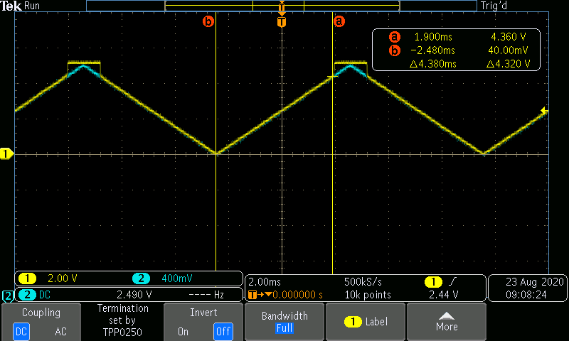
Signal input is a 1 Vpp triangle wave at 100 Hz with an offset of 2.5 VDC. Vcc is approximately 5.12 VDC from USB. Amplifier set for minimum gain of 5. Output voltage rises in a linear fashion as expected, but jumps to full-scale when the input exceeds approximately 0.85 VDC and remains there until the input drops below 0.85 VDC.

Schematic attached. Oscilloscope capture attached.

NOTE: The amplifier output channel is the yellow trace and the input is the blue trace. The attenuation on the output channel (yellow trace) for the scope is set to 1/5th that of the input and the two signals overlaid to illustrate the issue. I've tried removing the X2Y cap (C3 & C7) and resistors R3 and R8 to isolate the IN-Amps. There was no change in performance.

What am I doing wrong?

  • Hi Marvin,

    Thank you for your post, I can help you. At first glance, I am thinking that the output swing cannot go beyond 4.05V on a 5V single supply. While the INA332 is said to be rail-to-rail-out, that is for gains of 10V/V or more. Your circuit is in a gain of 5V/V. Note (2) on page 3 of the datasheet says "Output voltage swings are measured between the output and power-supply rails. Output swings to rail only if G ≥ 10. Output does not swing to positive rail if gain is less than 10."

    I am looking into this further for you to verify. In the interim, can you try reducing the Vref to 1.5V and test it again?

  • Thank you!

    I tried adding two gain resistors and sure enough the signal no longer had that strange flattop peak.  Instead, it followed the triangle wave just as expected.

    I guess I find it strange that TI would advertise a lower threshold gain of 5X when the behavior is so unusual.  

    I'll look into changing Vref to 1.5 VDC and let you know tomorrow.

  • Hi Marvin,

    After taking a look at this more closely, the reason why you see this behavior at gain = 5V/V is because A3 in the the instrumentation amplifier is not rail-to-rail in. On page 10 of the datasheet, it says that the output of V2 must be less than (VDD - 1.2V) for linear behavior. When VDD is 5V, that means the output of A2 must be below 3.8V.

    Take the example where the differential voltage applied to the input is 350mV, the output of A2 is 4.25V. This is beyond the linear range and so you get "clipped" behavior. If the circuit is in high enough gain, like 10V/V or more, then the inputs and outputs stay within linear range. 

    Hope that helps.

  • Thank you, Tamara.  I did try your suggestion to change the reference voltage to 1.5 volts, but that did not help.  I understand this is just a limitation of the part.  

    I appreciate the time  you took to help.

    Kind regards.

  • That's right, you'll get clipping in the other direction. I think adding gain is fixing the problem. Glad you were able to get that resolved. Please let me know if you run into any more issues moving forward, I will help you.

    Take care.