This thread has been locked.

If you have a related question, please click the "Ask a related question" button in the top right corner. The newly created question will be automatically linked to this question.

ISO124: ISO124 Supply Range and I/P impedance loading

Part Number: ISO124
Other Parts Discussed in Thread: ISO224
Hello Team,
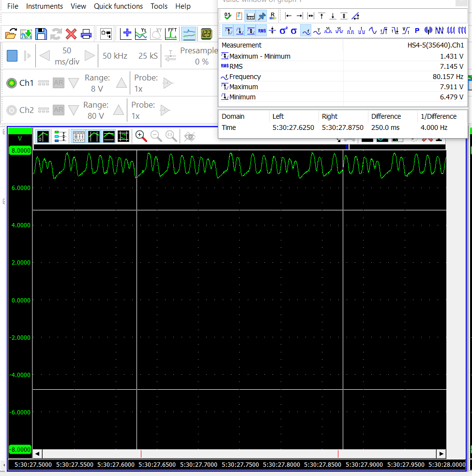
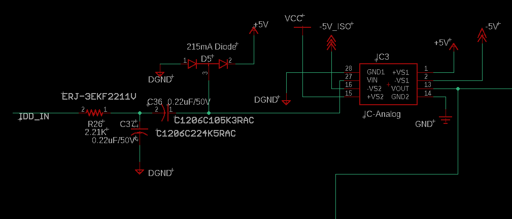
My Sensor signal which has 7V DC offset and 1.1V Vpp given as a Input to ISO124. I am Providing +/-5VDC as a VS1 and VS2 Supply. So, I m facing two problems here :
1. when i connect Sensor Signal to ISO124 input , its DC offset reduced by 1V, why ?
2. I am not able to see O/P signal from ISO124 , So should I increase the VS1 and VS2 Supply voltage ?
Max Sensor Freq is : 1Khz
I am attaching Input  Sensor signal and schematics for same.
Max Sensor Freq : 1Khz
  • Part Number: ISO124

    Sensor signal which has 7V DC offset and 1.1V Vpp. I am Providing +/-5VDC to VS1 and VS2 Supply. So, two problems here :
    1. when i connect Sensor Signal to ISO124 input , its DC offset reduced by 1V, why ?
    2. I am not able to see O/P signal from ISO124 , So should I increase the VS1 and VS2 Supply voltage ?
    Max Sensor Freq : 1Khz
     
  • Hi Bhupendra,

    The ISO124 requires some headroom on the supplies with regards to the input/output voltage. This is why the recommended operating conditions for the device are +/-15V supplies and a +/-10V input/output voltage. 

    If I understand you correctly, you are supplying +/-VS1 with +/-5V, while the input signal at it's peak is 7.55V - which is beyond the supply voltage. 

    I would recommend increasing the magnitude of the supply voltages as you have said. 

    The ISO224 is the new version of the ISO124 and can accept a +/-12V input using a uni polar 5V supply on the high-side. However, the ISO224 has a smaller package that may not be acceptable for more stringent isolation standards. 

    Please let me know if you have additional questions. 

  • Thanks alex,

    At present, Maximum I can give is +/-12V  as VS1 and VS2 , would it still possible to get +/-10V signal with this supply ?

    Moreover, first question remains unanswered:

    Input Sensor signal DC offset reduced by 1V (C36 O/P) , 

    when connect it to ISO124 Input , why ?

    Regards,

  • Hi Bhupendra,

    This device typically requires 2.5V of headroom from the supply to the input voltage. So I would expect that +/-9.5V to be possible using +/-12V supplies. 

    The device is currently being operated outside of the recommended conditions. The ISO124 is an older device and I'm not sure what internal protection features are present. It's possible that the ISO124 has an internal diode that is turning on in an attempt to protect the device form the over-voltage that is being applied. 

    Similarly, I see a diode structure on your input, D5, that is connected to 5V. The input voltage applied is higher in magnitude compared to this 5V, turning the diode on. 

  • Thanks for your update ......

    Still, first question remains unanswered:

    when we connect Sensor signal (C36 O/P) to ISO124 Input (High Side), It`s DC offset reduced by 1V  , why ? 

    Regards,

    Bhupendra

  • Hi Bhupendra,

    Please review my previous post more carefully. The diodes turning on in either situation could explain the voltage drop you are seeing. 

  • Thanks Team,

    This resolved my Problem. Pls. close this.