This thread has been locked.

If you have a related question, please click the "Ask a related question" button in the top right corner. The newly created question will be automatically linked to this question.

ISO224: ISO224 temperature issues

Part Number: ISO224
Other Parts Discussed in Thread: ISO124,

Hello everyone!

I recently moved my design from ISO124 to ISO224 because offset issues with ISO124. 

ISO224B is better in many aspects. My offset issues, mainly when temperature changes between measurements, were solved.

The problem is: ISO224 is showing a very poor gain stability against temperature changes. The temperature varies between +10ºC to +50ºC where the circuit is mounted.

I´m facing gain variation of 0,25% with this temperature range. ISO124U at the same conditions change the offset, but the gains remais stable (very small variations).

I thermally isolated ISO224 from the rest of my circuit to find the responsible for variations and I´m 100% sure that the problem is with ISO224B.

My question is: is there any analog isolator that can achieve the offset stability of ISO224 ang the gain stability of ISO124? Is there a circuit or any improvement to allow ISO224B became more stable with temperature variations (gain)? 

Thanks in advance!

Cristiano 

  • Hi Cristiano,

    The ISO224B gain drift is typically 10ppm/C. Starting from 25C, 50C is the maximum change with a delta of 25C (50C - 25C). 

    10ppm/C * 25C = 10*25/1000000 * 100 = 0.025%, 10x less than you are reporting.

    Given that all of our device are tested before leaving manufacturing - unless the device has been damaged in some way, you should not see this level of error. 

    How are you measuring the gain? Are you incorporating any other circuit components? 

    Is it possible that you have a calculation error, ie missing a 0 somewhere? 

    I recommend measuring directly at the inputs and outputs using a DMM. A schematic may help diagnose the issue as well. 

  • Hello Alexander,

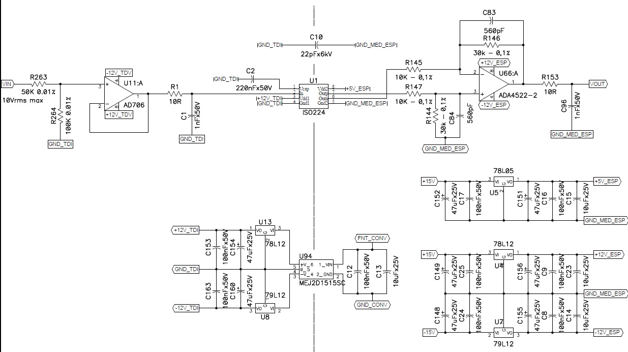
    Follow the schematic used for tests.  I´m measuring Vout and comparing it with Vin. Currently I´m using two Agilent 34411A as DMM, one for Vin and other for Vout.

    I did two different tests to validate the parts individually:

    - First I bypass my input circuit (AD706 and resistive divider) and insert 10Vdc signal to input. Did a measuring test with thermal variation (controlling the ambient temperature between 23ºC and 50ºC. In this case I observe variations caused by the change in temperature in order of 0.18%, in this scenario. I change the ISO224B for a new one and the results are similar (0.19%).

    - My second test was bypassing ISO224B. I removed it from PCB, direct connect pin 2 of ISO224 thru pin 3 of ADA4522-2. I let 10K resistors floating (similar to a buffer configuration). In this scenario, without ISO224B, I did a test with the same temperature variation. The variation observed was less than 0.02% (ten times smaller). (in this case I jump the GNDs togheter)

    There is a 22pF x 6kV Y type capacitor across the insulation to minimize DV/DT issues (ISO124U needs it to avoid spurios noise in our enviroment measures so I left it).

    I will perform some direct measurement on ISO224B output and return with results.

    Thanks.

    Cristiano

    PS.: I ran validate tests with 4 units labeled XISO224B and they work well. I found one last XISO224B and I´m test it rigth now. All ISO224B units are failling at the same tests performed with XISO224B.


  • Hi Cristiano,

    Thank you for providing additional information. 

    I would like to confirm that I understand your post script message correctly.

    You have 2 sets of devices. XISO224B and ISO224B. 

    XISO224B = Good results

    ISO224B = Bad results (10x worse)

  • Hi Alexander,

    Yes, I have two sets, one with XISO224B and ISO224B.

    After your first reply I started to suspect of my output circuit (ADA4522-2 and 10K + 30K 0.1% resistors). In my first test, when I bypass ISO224B I also ignore the resistors, using OpAmp as a buffer. In this case everything works fine.

    I return to my original circuit, using ISO224B, but I change 10K + 30K resistors (0.1% and 25ppm/ºC) to metal foil ones (0.01% and 2ppm/ºC). I´m running the tests rigth now and seems to work fine. I´m suspecting the 0.1% resistors are not working according specifications (thermal stability is worse than expected). 

    I believe I will have final results tomorrow then I return with more informations.

    Cristiano


  • Hi Cristiano,

    Just checking in about those final results?