This thread has been locked.

If you have a related question, please click the "Ask a related question" button in the top right corner. The newly created question will be automatically linked to this question.

Safety Measures in Constructing EMG Amplifiers

Other Parts Discussed in Thread: OPA2604, ISO124, INA128, INA111

Hello Everyone!

Im currently working on my university final year project. My project is about constructing two similar EMG circuits (but differing in gain) to measure EMG from two forearm muscles called the Flexor Digitorum Superficialis (FDS) and Extensor Carpi Radialis Longus (ECRL). The outputs from the EMG circuits will be connected directly to a National Instruments SCC-68 Connector block with a PCI-6221 DAQ and computer running Labview 8.6 software. The purpose of this project is to find the relationship between the EMG signals measured from the forearm muscles to hand grip strength (measured using a hand dynamometer sensor). Experimental measurements from the EMG are to be taken while im gripping a hand dynamometer.

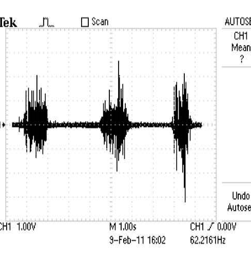
I have included an image of the EMG waveform from the circuit I have constructed to measure EMG from the Flexor Digitorum Superficialis muscle below. I have also included the circuit schematic I have used together with results from a short experiment I conducted to find the relationship between EMG frequency and hand grip strength. 6180.EMG_circuit.pdf

I used the INA128P instrumentation amplifer and OPA2604 operational amplifier for the band pass filters filters and additional stages. I used the driven right leg circuit to reduce common mode noise. Each of these circuits are powered by two energizer 9V batteries to supply +9V and -9V to each IC, therefore a total of four 9V batteries are used to power both the EMG circuits.

Since Im planning to connect the output of these EMG circuits to a National Instruments SCC-68 Connector block with a PCI-6221 DAQ and computer running Labview 8.6 software (which is powered by the wall socket power supply), what components should I include/add to this circuit  in order to protect the subject? I have come across safety measures such as using the ISO124 isolation amplifier and optocouplers such as the HCNR200/201. This is a university class project and its not meant for medical or commercial purposes. I am working under the supervision of my lecturer.
  • Ahmad,

    You are wise to be concerned when acquiring signals with electrodes on the body.

    When connecting to AC-mains-powered equipment you should provide galvanic isolation in the signal path. The ISO124 is, of course, galvanically isolated. The input side of the ISO124 and all input circuitry must then be powered from batteries or other galvanically isolated source. By the way, the ISO124 is not generally considered suitable for commercial medical products as its isolation voltage rating does not meet medical standards. Medical standards generally require a device to withstand a defibulator pulse of 8000 volts without damage. Still it may be sufficient for your application.

    Another possibility is to acquire an input module from National Instruments that internal isolation. I believe they offer such products.

    Your circuitry has some inherent additional safety due to the 100k input resistors. It takes approximately 1mA current in the body to create sensation. A few milliamps is considered undesirable. Over 10 milliamps can become painful. It would require 100V across a 100k resistors to create 1mA current so a substantial voltage fault condition would be required to cause a problem.

    With that said, the 100k input resistors may be causing you some issues. Their thermal noise and the noise produced by the input current noise of the INA128 flowing through these resistors is substantial. You can see this noise and judge for yourself. Connect the two input electrodes to the active ground electrode and check the noise level. Is it much smaller than the signals you are measuring? Reducing the input resistors to 10k or so would substantially reduce this noise. You, of course, would lose some level of safety. If galvanic isolation is provided, this is probably not a concern.

    Another problem encountered when acquiring electrical signals from the body is variable contact resistance. The input bias currents of the INA128 reacting with this variable contact resistance can cause artifacts that can be confused with your desired signals. If the subject is trembling, for example, while squeezing, varying contact resistance may produce a significant artifact. You may want to try the INA111 instead of the INA128. This amplifier has FET inputs with very low input bias current and would virtually eliminate these artifacts. It would also eliminate the noise produced by input bias current (previous paragraph).

    So far as safety is concerned, only you and your advisers can judge what is appropriate for the situation. I recommend galvanic isolation.

    Regards, Bruce.


  • Hi Bruce

    Does the same rule apply to battery driven equipment and have you any suggestions of how to provide 8kV of isolation for mains driven equipment.

    Thanks


    Des

  • Des,

    You ask about a "rule" but I am not an expert on safety standards that may apply. I believe that a small battery powered instrument that does not connect to other equipment would not require galvanic isolation in its signal chain. It would need to be fully insulated so that no accendental contact could be made to any circuitry or circuit ground. A metal enclosure connected to the circuit ground would be not be safe. No exposed metal hardware could be connected to circuitry or ground.

    Isolation is commonly achieved with optical isolators. Often the signal is digitized prior to isolation so that digital isolators can be used.

    Regards, Bruce.