This thread has been locked.

If you have a related question, please click the "Ask a related question" button in the top right corner. The newly created question will be automatically linked to this question.

AMC1300B-Q1: Viewing Output of isolated shunt amplifier directly on oscilloscope

Part Number: AMC1300B-Q1


Hi,

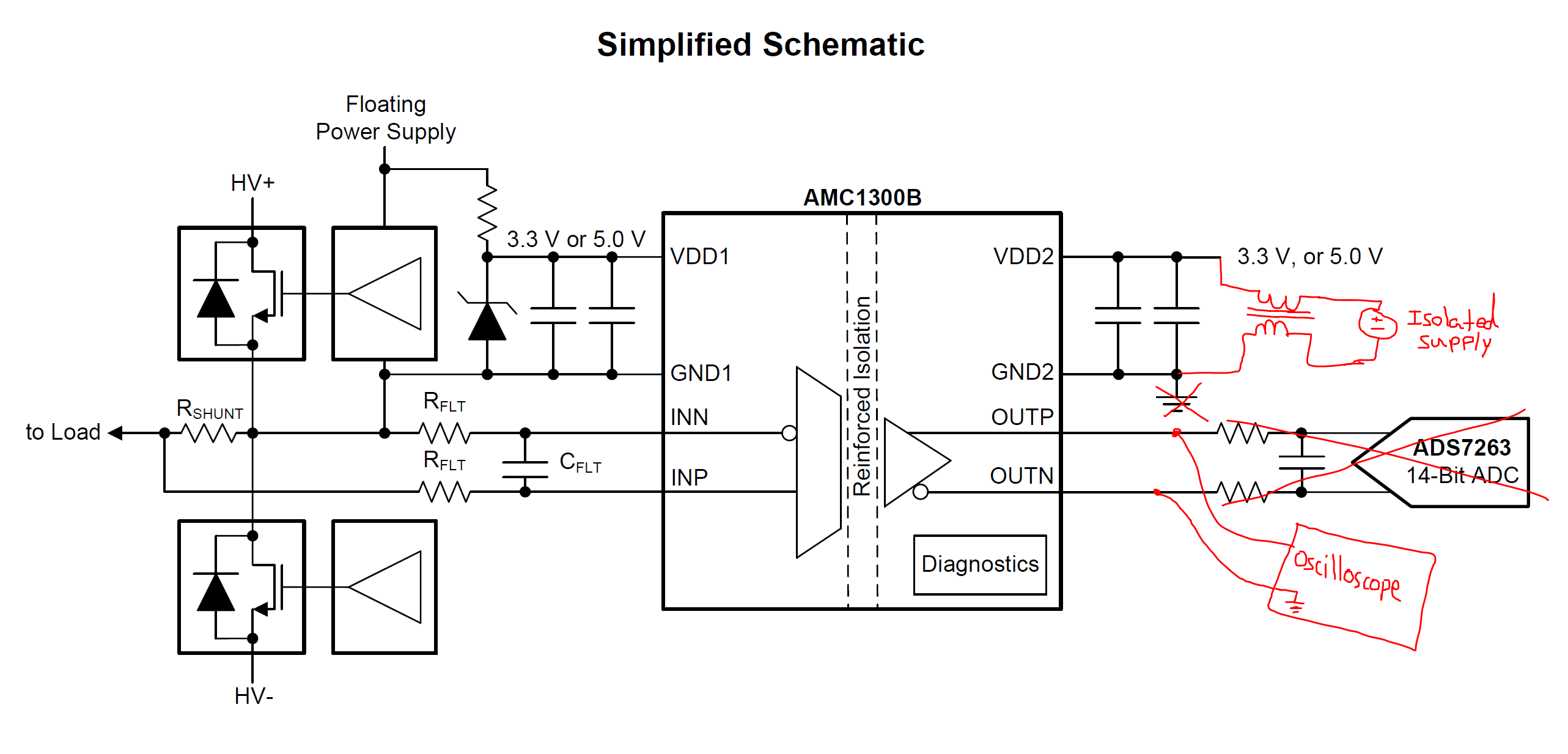
Does it cause bias current problems to supply an isolated shunt amplifier like the AMC1300B-Q1 with an isolated supply and then to look at the output with a single-ended oscilloscope probe (which grounds the OUTN pin)? The Riedon SSA series of isolated shunt resistors use one of the TI isolated shunt amplifiers, and I would like to use it as an oscilloscope current probe. I'm not sure if this is problematic for the amplifier output since there isn't a path for positive bias current from OUTN or OUTP to COM. I bought a cheap USB charger to power the amplifier (isolated, with very low capacitance to ac input), and it worked, though the output was quite noisy unless I add a CM choke to the VDD2/GND2 supply. It was even noisier with a benchtop linear supply (and no CM choke), likely due to the higher capacitance to ground.

Also, am I correct to assume that using 50 Ohm termination setting on the scope in this configuration would exceed the current rating of the amplifier output? That would be up to (+/-0.32V*8.2V/V)/50 ohm = +/-52.5 mA, and the AMC1300B-Q1 datasheet lists the output short-circuit current as +/-13mA typ.

--------

Edit: updated to clarify use of single-ended scope probe.

  • Hi Andrew,

    This looks to be a very unique application. It is typically not necessary to supply VDD2 with an isolated supply - just VDD1. What is the reason for this?

    OUTP/N should not be directly tied to ground as it is a driven output. I recommend adding a 10kohm resistor to limit the current. 

  • hi Alex,

    There is a shunt resistor product that uses one of these amplifiers, and brings out VDD2, GND2, OUTP, and OUTN.  I would like to view the output of the amplifier directly on the scope, using it as a current probe. The straight forward way would be to use two scope channels , one from OUTP to GND2, and one from OUTN to GND2, and subtract the two to get the output. However, I wanted to use the single ended oscilloscope measurement from OUTP to OUTN, which would tie OUTN to the oscilloscope ground (see marked up schematic in first post). Thus GND2 can’t be tied to earth ground or it would be shorted to OUTN through the scope ground. Is that a problem in terms of bias currents on the amplifier output?

  • Hi Andrew,

    I haven't tried this myself, but in theory I think it should work. However, I would still recommended adding an additional resistor to limit the current as 50ohms as you've pointed out could draw significant current.